Lower leg prosthesis

a lower leg and prosthesis technology, applied in the field of lower leg prosthesis, can solve the problems of limited upward deflection of the heel section of the foot plate, and achieve the effects of improving inversion/eversion compliance, and improving the dynamic feel of the heel strik

Inactive Publication Date: 2002-09-12
OTTO BOCK HEALTHCARE IP GMBH & CO KG
View PDF6 Cites 33 Cited by
  • Summary
  • Abstract
  • Description
  • Claims
  • Application Information

AI Technical Summary

Benefits of technology

0006] The present invention is embodied in an improved lower leg prosthesis that, during use, provides an improved dynamic feel at heel strike and that provides improved inversion / eversion compliance. The prosthesis includes an elongated pylon having an upper, generally vertical section and a lower, forwardly oriented foot section, wherein the upper section defines a vertical pylon axis, and it further includes a generally horizontally oriented foot plate disposed beneath the pylon and including a heel section projecting a substantial distance rearwardly of the vertical pylon axis. The pylon and the foot plate both are formed of a high-strength composite material, e.g., an epoxy / carbon fiber composite material. Further, an elastomeric layer, e.g., formed of a high-density polyurethane material, is interposed between the pylon and the foot plate, extending along substantially the entire length of the heel section of the foot plate, for attaching the pylon and foot plate together. During use of the prosthesis, at heel strike, upward deflection of the foot plate's heel section is limited in substantial part both by the stiffness of the heel section, itself, and by compression of the portion of the elastomeric layer disposed rearwardly of the vertical pylon axis.
0007] In a more detailed feature of the invention, the forward tip of the foot plate is disposed substantially beneath the forward tip of the pylon's forwardly oriented foot section, and the elastomeric layer extends along substantially the entire length of the foot plate, from its forward tip to the rearward tip. The elastomeric layer preferably has a width that tapers from a minimum at the foot plate's forward tip to a maximum at a mid-portion of the foot plate to a minimum at the foot plate's rearward tip. In addition, the pylon's forwardly oriented foot section has a width that tapers from a maximum at a location substantially aligned with the maximum width of the elastomeric layer to a minimum at the foot section's forward tip. The points of maximum width of the pylon's forwardly oriented foot section and the elastomeric layer preferably are located forward of the vertical pylon axis.
0008] In other more detailed features of the invention, the portion of the elastomeric layer disposed on the heel section of the foot plate has a concave upper surface. This concave upper surface preferably is a circular arc, substantially tangent both to the pylon's upper, vertical section and to the foot plate's rearward tip.
0009] The portion of the elastomeric layer disposed rearwardly of the vertical pylon axis preferably provides at least about one-third of the total resistance to upward flexing of the foot plate's heel section at heel strike. In addition, this layer has a thickness of at least about one-half centimeter along substantially its entire length.

Problems solved by technology

During use of the prosthesis, at heel strike, upward deflection of the foot plate's heel section is limited in substantial part both by the stiffness of the heel section, itself, and by compression of the portion of the elastomeric layer disposed rearwardly of the vertical pylon axis.

Method used


Image

  • Lower leg prosthesis
  • Lower leg prosthesis
  • Lower leg prosthesis

Examples


Embodiment Construction

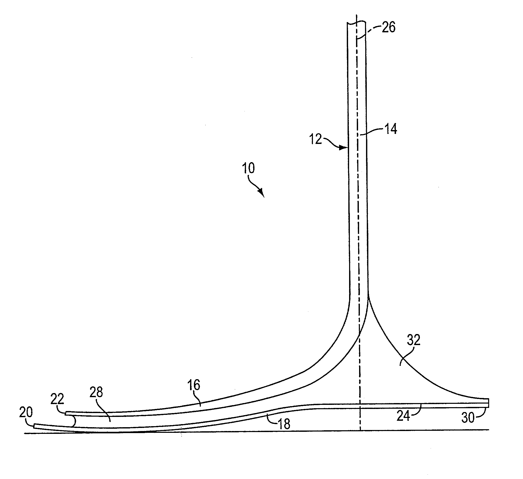
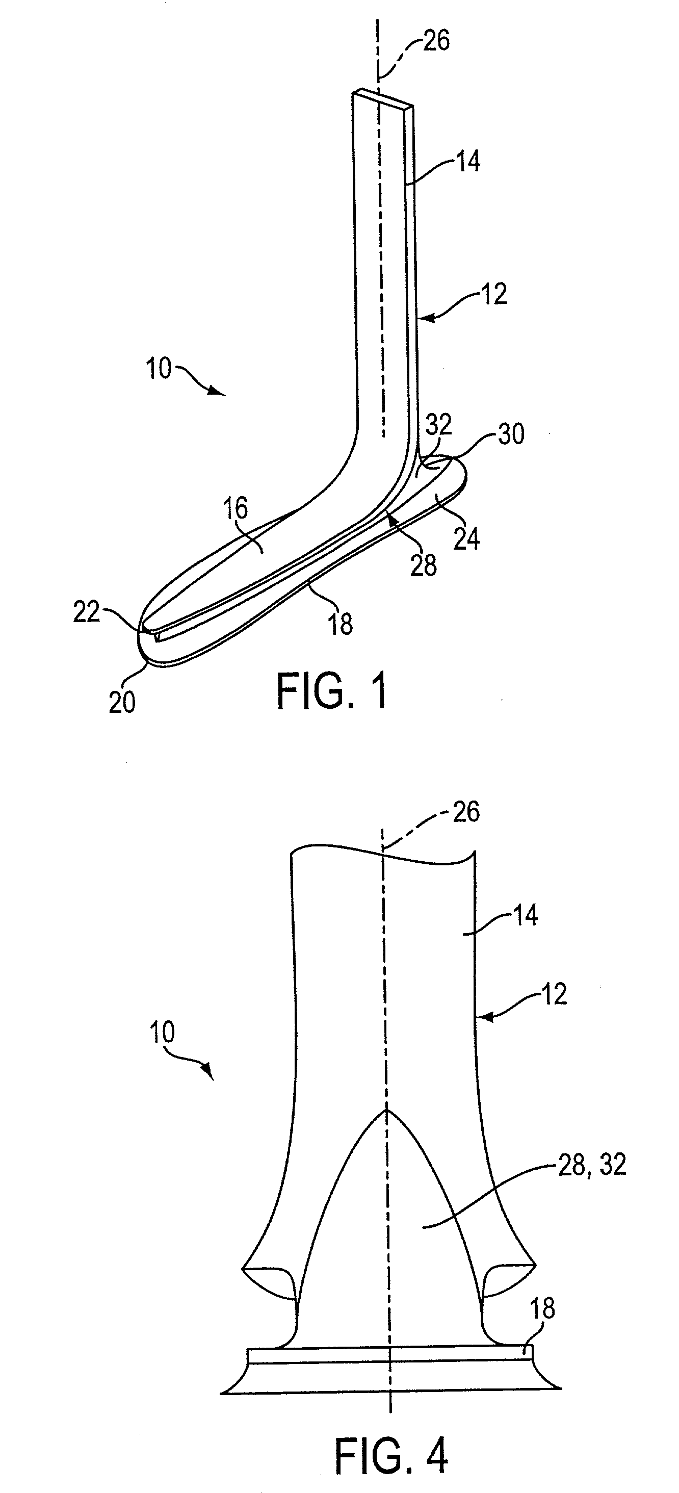
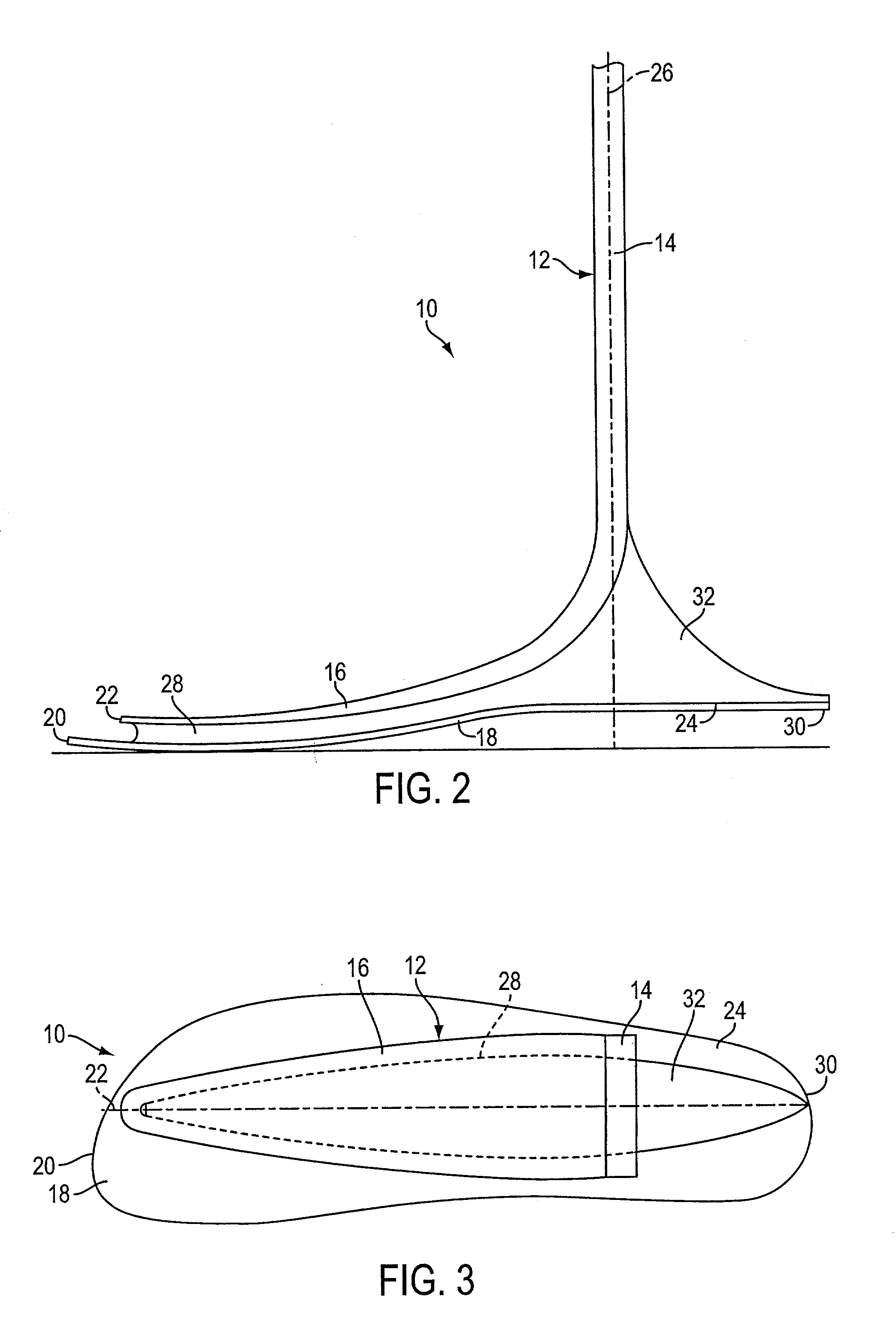
[0016] With reference now to the illustrative drawings, and particularly to FIGS. 1-4, there is shown a lower leg prosthesis 10 in accordance with the invention, the prosthesis incorporating an elongated pylon 12 having an upper, vertically oriented ankle / shin section 14 and a lower, forwardly oriented forefoot section 16, and further incorporating an underlying foot plate 18. As best shown in FIG. 2, the forward tip 20 of the foot plate is disposed substantially beneath the forward tip 22 of the pylon's forefoot section. In addition, the foot plate's rearward end defines a heel section 24 that projects rearwardly of a vertical axis 26 defined by the pylon's ankle / shin section. An elastomeric layer 28 extends along substantially the entire length of the foot-plate, or permanently attaching the foot plate to the pylon. The prosthesis duplicates the dynamic performance characteristics of the normal human foot, yet it is of simple construction and can be manufactured relatively inexpen...


PUM


Abstract

An improved lower leg prosthesis is disclosed that, during use, provides an improved dynamic feel at heel strike and that provides improved inversion/eversion compliance. The prosthesis includes an elongated pylon having an upper, generally vertical section and a lower, forwardly oriented foot section, and it further includes a generally horizontally oriented foot plate disposed beneath the pylon and including a heel section projecting a substantial distance rearwardly of a vertical pylon axis. An elastomeric layer is interposed between the pylon and the foot plate, extending along substantially the entire length of the heel section of the foot plate, for attaching the pylon and foot plate together. During use of the prosthesis, at heel strike, upward deflection of the foot plate's heel section is limited in substantial part both by the stiffness of the heel section, itself, and by compression of the portion of the elastomeric layer disposed rearwardly of the vertical pylon axis.

Description

BACKGROUND OF THE INVENTION[0001] This invention relates generally to lower leg prostheses and, more particularly, to lower leg prostheses configured to duplicate the dynamic performance characteristics of the human foot and ankle.[0002] Significant advancements in the field of lower leg prostheses have been made in recent years, due largely to the development of composite materials technology. Lower leg prostheses incorporating fiberglass / epoxy and carbon fiber / epoxy composite materials have been developed, which closely duplicate the dynamic performance characteristics of the human foot and ankle.[0003] One such lower leg prosthesis is disclosed in U.S. Pat. No. 4,959,073 issued to Merlette. The Merlette prosthesis incorporates an elongated composite main member having a leg section and a forwardly extending foot section, and it further incorporates a heel member projecting rearwardly from the underside of the main member's foot section. A high-density polyurethane elastomer is di...

Claims


Application Information

Patent Timeline
Patent Type & Authority Applications(United States)
IPC IPC(8): A61F2/60A61F2/66
CPCA61F2/60A61F2/66A61F2002/607A61F2002/6614A61F2002/6657
Inventor MERLETTE, JOHN B.RUBIE, ERIC W.WALL, DAVID J.BRUEGGEMANN, JAMES R.
Owner OTTO BOCK HEALTHCARE IP GMBH & CO KG
Why Eureka
Try Eureka