Method and system for monitoring an apparatus for a computer

a technology for monitoring systems and computers, applied in program control, data switching networks, instruments, etc., can solve problems such as uninterruptible power supply, data loss, and requiring a significant amount of storage and ram

Inactive Publication Date: 2002-09-12
LIEBERT
View PDF46 Cites 74 Cited by
  • Summary
  • Abstract
  • Description
  • Claims
  • Application Information

AI Technical Summary

Benefits of technology

0009] In view of the foregoing and other considerations, the present invention relates to a system that monitors an apparatus, such as an uninterruptible power supply (UPS). The system determines the potential effect of the apparatus on computers in a network, such as the ability of the UPS to handle the load connected to it, and signals the computers on the network to perform an orderly shutdown, if necessary.

Problems solved by technology

For example, an uninterruptible power supply (UPS) provides power to computers and other devices in a network during disturbances in commercial power.
When the batteries in the UPS have completely discharged, loss of data will occur if proper steps are not taken to protect the data.
Conventional programs on the computers may have an extensive graphical user interface, requiring a significant amount of storage and RAM on each computer in the network.
In addition, a network may use any of a number of computer operating systems, and an extensive GUI environment limits the portability of a monitoring system to various operating systems.
Furthermore, installation of the conventional program of the computers on the network requires difficult and lengthy configuration.
Given that a network may have upwards of five thousand workstations, installing and updating the programs on each of the computers is labor intensive.
Due to the difficulties described above, most of the computers on a network are not properly equipped with shutdown software.

Method used


Image

  • Method and system for monitoring an apparatus for a computer
  • Method and system for monitoring an apparatus for a computer
  • Method and system for monitoring an apparatus for a computer

Examples


Embodiment Construction

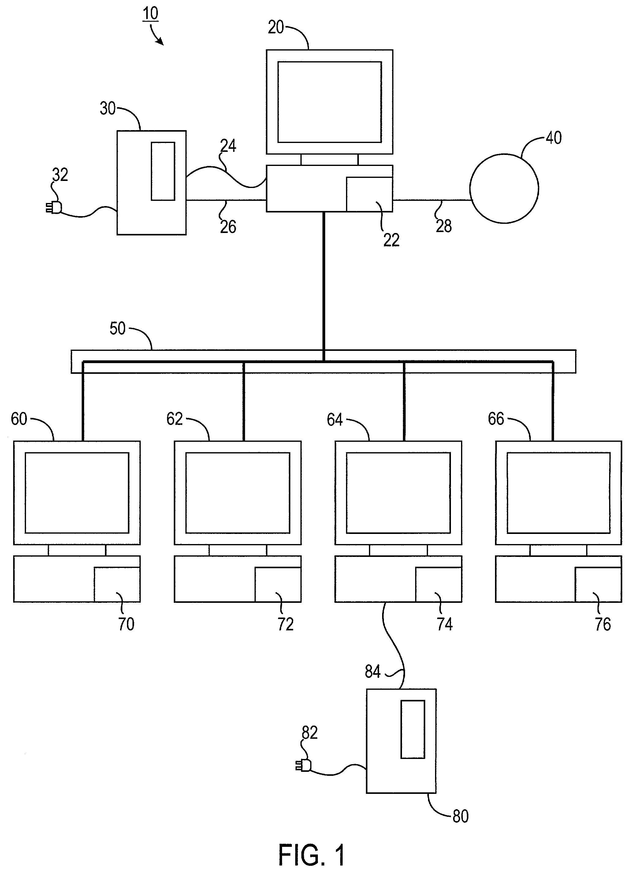
[0021] Referring to FIG. 1, a monitoring system 10 according to the present invention is illustrated deployed across a network 50. The monitoring system 10 includes a monitoring program 22 installed on a monitoring computer 20 connected to network 50. Monitoring system 10 also includes a plurality of pre-configured subordinate programs 70, 72, 74, and 76 installed on target computers 60, 62, 64, and 66 also connected to network 50. Monitoring computer 20 can be a server, which manages common data and peripherals for network 50. Alternatively, monitoring computer 20 can be any computer on network 50 having monitoring program 22. Target computers 60, 62, 64, and 66 can be workstations using monitoring computer 20 as a server or can be other computers on network 50.

[0022] Monitoring program 22 is designated to monitor one or more apparatus or devices 30, 40, and 80. In a preferred embodiment, the monitored apparatus 30 is an uninterruptible power supply (UPS), which connects to a conve...


PUM


Abstract

A system for monitoring various support devices of a computer network is disclosed. The network has a monitoring computer with a monitoring program that monitors the devices. The monitoring program is used to configure a subordinate program. Using push technology, the subordinate program is installed on and is run on target computers in the network. The monitoring program monitors operating parameters and alarm signals from the devices. When the monitoring program determines that the devices can no longer support its load, the monitoring computers sends a shut down instruction to the affected target computers. The subordinate program executes a shutdown routine for the target computer based on the shutdown instruction sent from the monitoring program. The subordinate program has minimal or no graphical user interface on the target computer and requires no local configuration by the user of the target computer.

Description

CROSS-REFERENCE TO RELATED APPLICATIONS[0001] This application claims the benefit of the Provisional Application Serial No. 60 / 272,664 filed Mar. 1, 2001.FIELD OF THE INVENTION[0002] The present invention relates generally to a monitoring system for a computer, and more particularly to, a system for monitoring an apparatus or device, such as an uninterruptible power supply (UPS), for a computer on a network.BACKGROUND OF THE INVENTION[0003] Computers in a network depend on a number of devices to provide power, ensure operating parameters, or maintain environmental conditions. Such devices include power supply, distribution and conditioning devices environmental monitoring and control devices and other facility monitoring and control devices. For example, an uninterruptible power supply (UPS) provides power to computers and other devices in a network during disturbances in commercial power. The UPS uses an auxiliary power source, such as batteries, to power the equipment in the netwo...

Claims


Application Information

Patent Timeline
Patent Type & Authority Applications(United States)
IPC IPC(8): G06F11/00G06F11/30H04L12/26
CPCG06F11/004G06F11/3013G06F11/3055G06F11/3093H04L43/00H04L43/045H04L43/0817
Inventor VELTEN, MIKECLEMANS, BRIANWORCESTER, WIN
Owner LIEBERT
Why Eureka
Try Eureka