Rotating electrical machine

a technology of electrical machines and rotating shafts, which is applied in the direction of dynamo-electric components, magnetic circuit shapes/forms/construction, cooling/ventilation arrangements, etc., can solve the problems of cooling medium leakage from the juncture of stator cores with resinous materials, adversely affecting the rotating efficiency of rotating electric machines, etc., and achieves the effect of improving the sealing characteristics of resinous materials

Inactive Publication Date: 2002-09-19
NISSAN MOTOR CO LTD
View PDF0 Cites 21 Cited by
  • Summary
  • Abstract
  • Description
  • Claims
  • Application Information

AI Technical Summary

Benefits of technology

0004] It is therefore an object of this invention to improve the sealing characteristics of the resinous material with respect to the stator core.

Problems solved by technology

Since the conventional example of a rotating electrical machine displays poor sealing characteristics between the stator core and the resinous material, the cooling medium may leak from the juncture of the stator core with the resinous material.
Leakage of cooling medium from the inner peripheral surface of the stator towards the rotor increases friction during rotation of the rotor and therefore adversely affects the rotating efficiency of the rotating electric machine.

Method used


Image

  • Rotating electrical machine
  • Rotating electrical machine
  • Rotating electrical machine

Examples


second embodiment

[0052] In the second embodiment, a T-shaped end plate 35 is formed so that the shape of the end plate 35 which is disposed on both ends of the stator core 20 substantially coincides with the shape of the divided core 21 (core component). A plurality of end plates substantially cover the whole end of the stator core 20.

[0053] In this manner, a wire cross over section 30A between the coils 30 avoids direct contact with the end face of the stator core 20 and thus avoids damage to the wire as a result.

[0054] Referring to FIGS. 12A-12C, avoiding damage to the lead wire section 30B of the coils 30 is enabled by forming a curved section 35B. The curved section 35B leads the lead wire section 30B of the coils 30 onto one shoulder 35A of the end plate 35.

[0055] Next a third embodiment of this invention will be described referring to FIG. 13 and FIG. 14. This embodiment differs from the first embodiment with reference to the shape of the end plate. However in other respect, this embodiment is...

third embodiment

[0056] In the third embodiment, a step 71A is formed on an end face of the end plate 71 as an engaging section extending in parallel along the inner periphery 5A of the stator 5, as shown by FIG. 13, FIGS. 14A and 14B. The step 71A engages with the cylindrical member 14.

[0057] The step 71A increases the bonding of the end plate 71 with the resinous material constituting the resin-molded cylindrical member 14.

first embodiment

[0058] Referring to FIGS. 15A and 15B, during the manufacturing of the cylindrical member 14, a columnar inner mold 61 is disposed in tight attachment with the inner periphery of the stator 5 in the same manner as the first embodiment and a cylindrical outer mold 62 is disposed on an outer side of the inner mold 61 at both ends of the stator 5. A cylindrical space SP1 is partitioned by creating a fixed gap between the molds 61 and 62. A resinous material is introduced to fill the space formed by the molds 61, 62.


PUM


Abstract

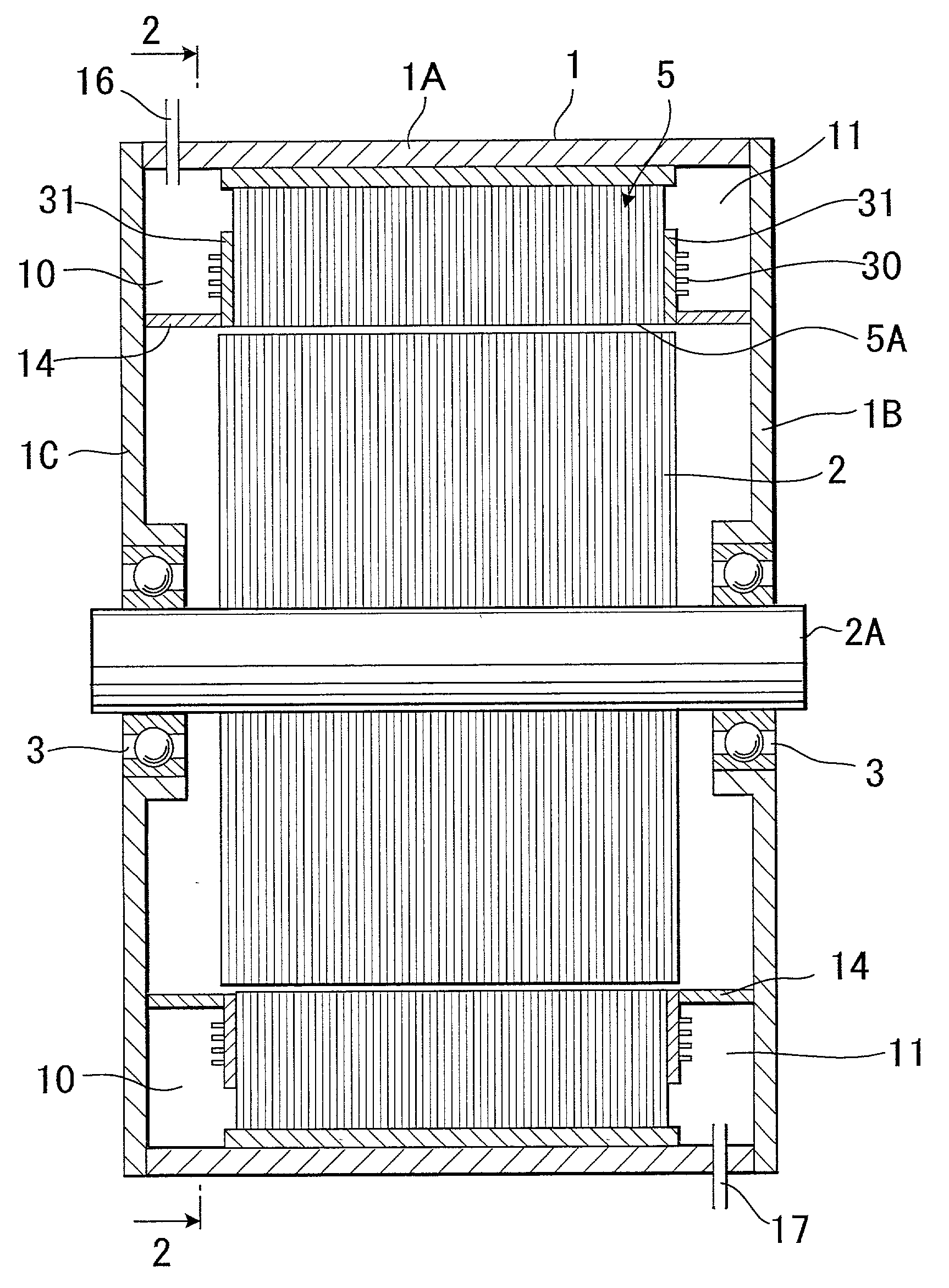
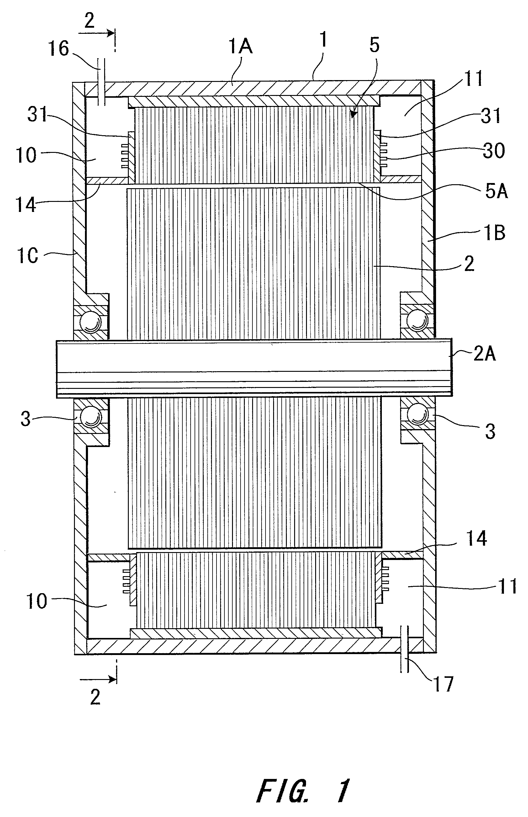
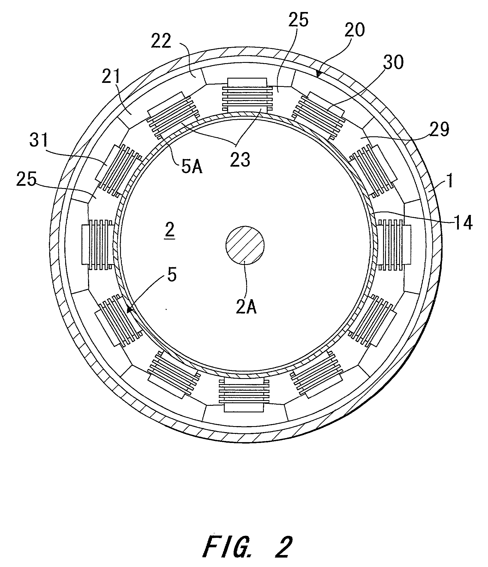
This invention prevents leakage of cooling medium from a cooling passage in the interior section of a slot of a stator. Coils are housed in the slot of the stator core. The openings of the slot are covered in order to form a cooling passage in the slot. An end plate is disposed on the end of the stator. The stator core and the end plate are integrated by winding coils through the outer side of the end plate. A cylindrical member which projects along the inner peripheral face of the stator from the end of the stator is formed by resin molding to be integrated with a section of the end plate. A ring-shaped space which introduces cooling medium is formed on an outer peripheral side of the cylindrical member and is connected with the cooling passage.

Description

FIELD OF THE INVENTION[0001] This invention relates to a rotating electrical machine (a motor or a generator, or a motor / generator) which has a cooling mechanism.BACKGROUND OF THE INVENTION[0002] Tokkai Hei 4-364343 published by the Japanese Patent Office in 1992 discloses a rotating electrical machine which uses an inner section of a slot of a stator as a cooling passage. In this rotating electrical machine, components which generate heat such as the stator coils or the stator can be directly cooled by coming into direct contact with a cooling medium, for example a cooling oil, which flows in the slot. When forming the cooling passage, a mold is disposed in the inner section of the slot and on the inner periphery of the stator. A resinous material is injected in order to fill the space defined by the stator core and the mold. The resinous material hardens and covers the slot opening.SUMMARY OF THE INVENTION[0003] Since the conventional example of a rotating electrical machine displ...

Claims


Application Information

Patent Timeline
Patent Type & Authority Applications(United States)
IPC IPC(8): H02K5/128H02K9/197
CPCH02K5/128H02K9/197
Inventor KIKUCHI, TOSHIOKITADA, SHINICHIROKANEKO, YUTAROTSUNEYOSHI, TAKASHI
Owner NISSAN MOTOR CO LTD
Why Eureka
Try Eureka