Noise reduction system for kitchen

Inactive Publication Date: 2002-09-26
OWENS CORNING FIBERGLAS TECH INC
View PDF0 Cites 44 Cited by
  • Summary
  • Abstract
  • Description
  • Claims
  • Application Information

AI Technical Summary

Benefits of technology

0008] The present invention, also in part, is a recognition that the kitchen environment usually has the least amount of energy reduction materials of any room in the home. Therefore, it is an object of the present invention to provide a noise reduction system for improving the noise reduction characteristics of the environment in which kitchen appliances will operate.
0009] The components of the present invention will reduce the acoustic energy transmitted from appliances

Problems solved by technology

However, the kitchen conventionally has the least amount of energy reduction materials of any room in the home.
The characteristics of the environment in which these same appliances or machines are intended to operate will often have a negative effect on any efforts aimed exc

Method used


Image

  • Noise reduction system for kitchen
  • Noise reduction system for kitchen
  • Noise reduction system for kitchen

Examples


Embodiment Construction

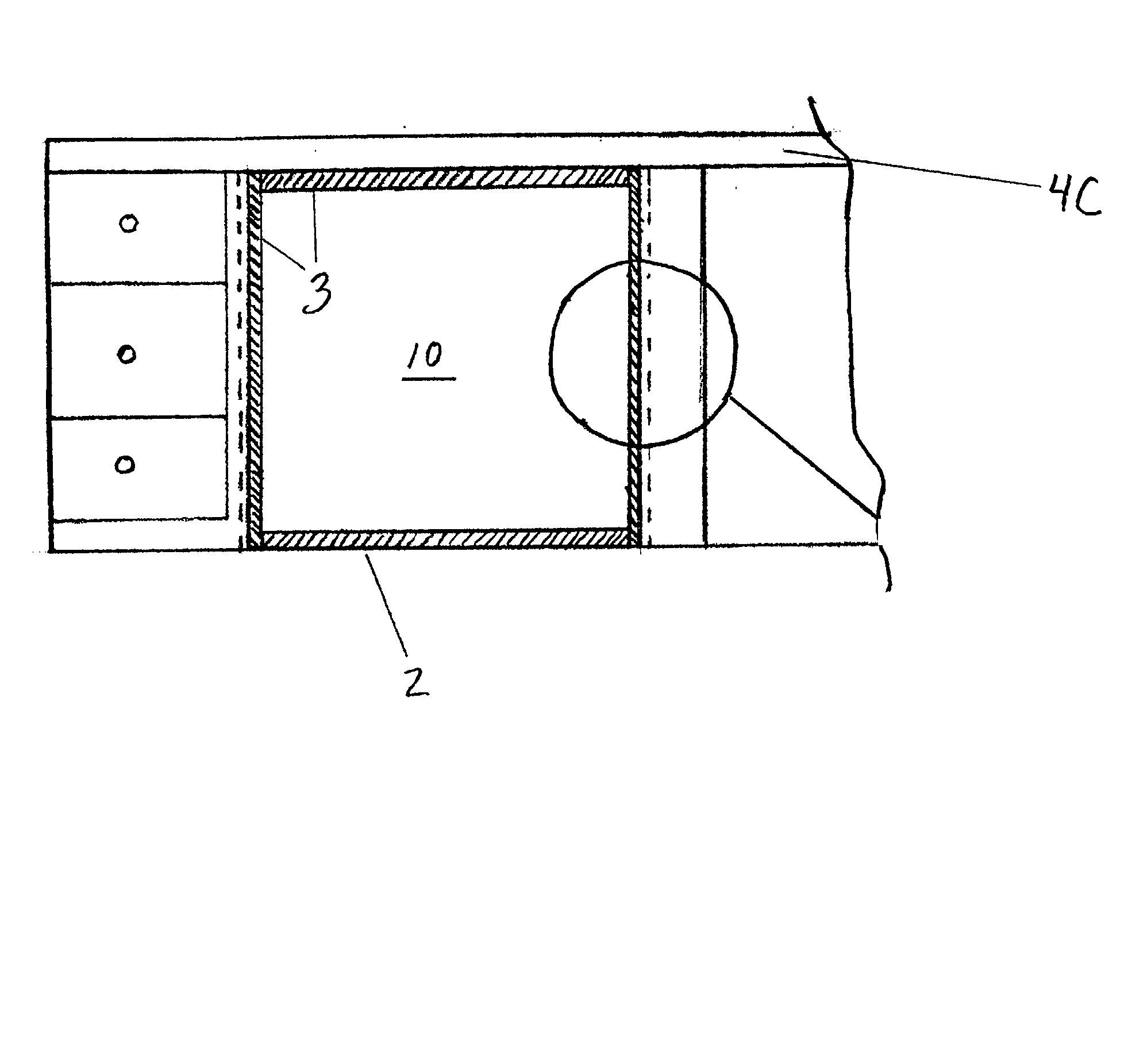
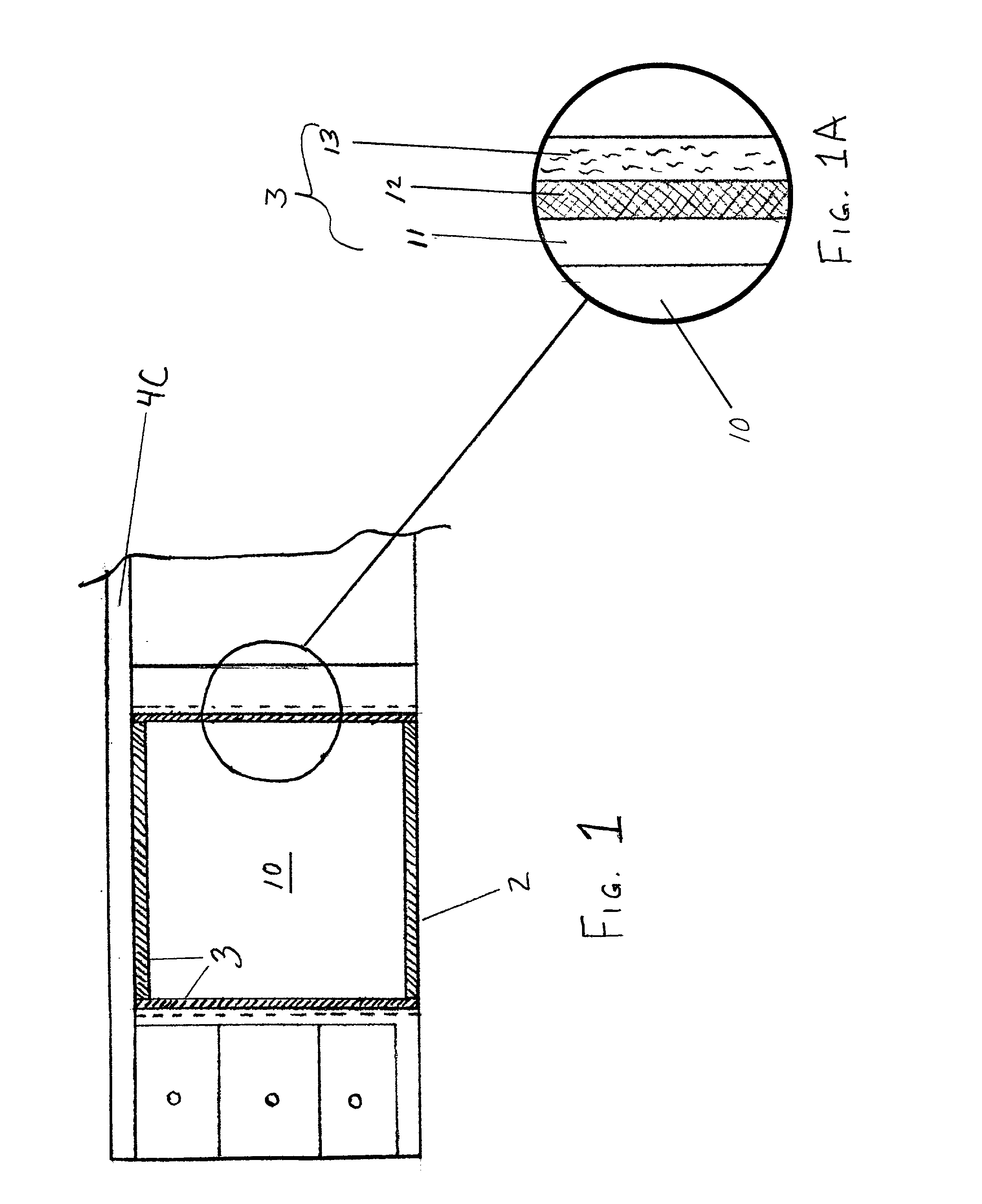
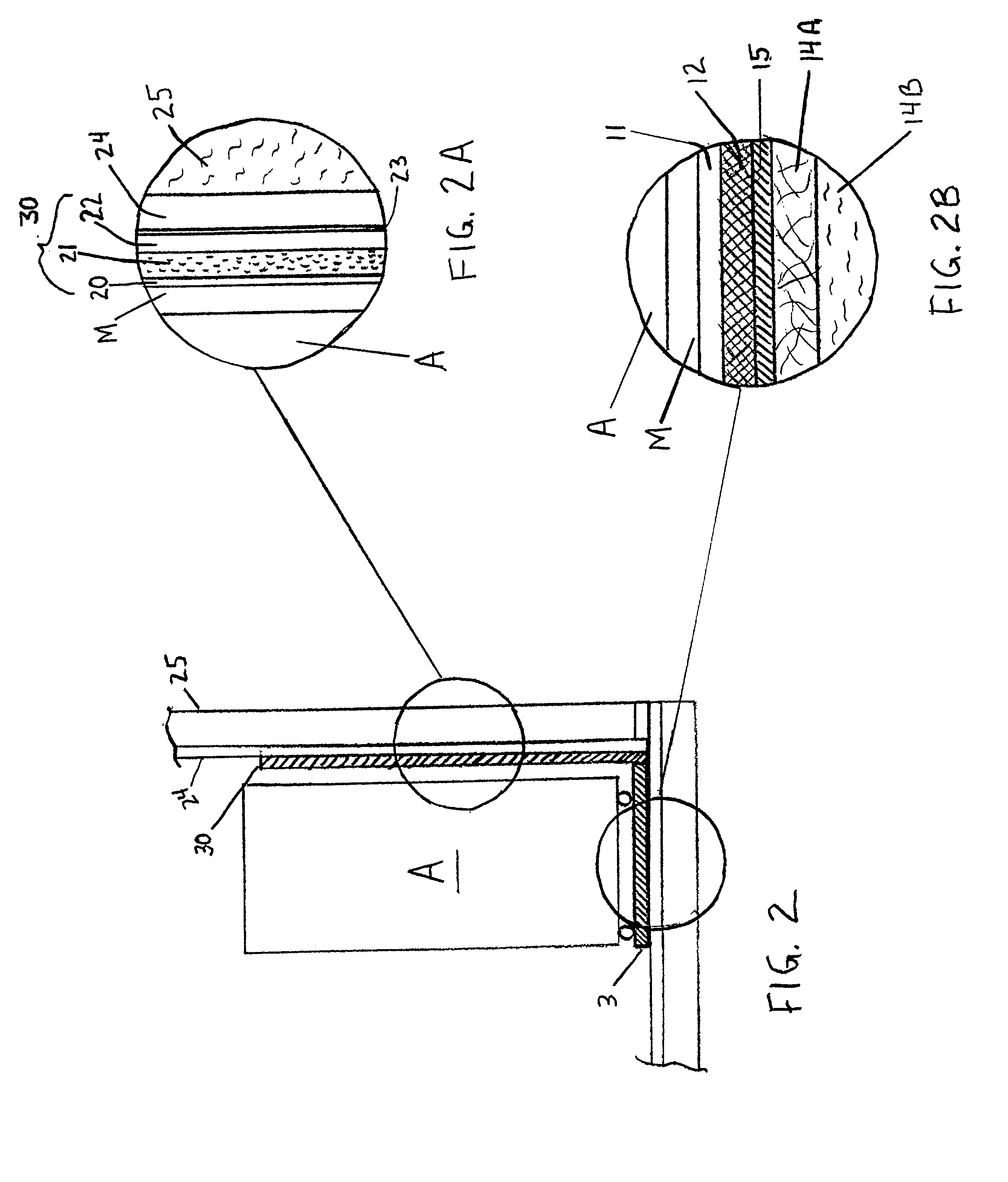
[0027] The components of this present invention will reduce the acoustic energy transmitted from the appliances to the kitchen environment by resisting the transmission of vibro-acoustic energy through the cabinetry, flooring and walls. The components of this present invention have been designed to isolate as well as dissipate vibro-acoustic energy. By isolating and dissipating the vibro-acoustic energy, the noise radiated into the kitchen will be reduced. This will improve the atmosphere of the kitchen and improve communication within the kitchen by lowering background sound levels due to appliances and other kitchen apparatus.

[0028] As discussed hereinabove, prior efforts have shown that this noise can be reduced with targeted, frequency specific, dissipation. However, one of the aspects of the present invention, in part, is that it has been determined that the transmission of vibro-acoustic energy can be controlled by the application of mass based treatments to the cabinets, isol...


PUM


Abstract

A method and system of achieving noise reduction in a kitchen environment is disclosed. Noise reduction is achieved through the application of transmission loss paneling, sound absorption paneling, and vibro-acoustical isolation paneling to surfaces of a kitchen environment surrounding typical kitchen appliances. Targeted, noise reduction of the kitchen environment is achieved by installing the noise reduction system of the present invention to walls, cabinetry and flooring of a typical kitchen environment.

Description

TECHNICAL FIELD AND INDUSTRIAL APPLICABILITY OF THE INVENTION[0001] The present invention is generally directed to a noise reduction system for a kitchen, and more particularly to a noise reduction system and method designed to reduce targeted emissions from appliances and structure associated with the kitchen.BACKGROUND OF THE PRESENT INVENTION[0002] Currently the kitchen environment is recognized as one of the loudest rooms within the home. However, the kitchen conventionally has the least amount of energy reduction materials of any room in the home. Some related noise reduction techniques of the conventional art have been aimed at noise reduction of the machines or appliances themselves.[0003] For example, U.S. Pat. No. 5,855,353 to Shaffer et al. teaches a method and apparatus for damping vibration in a vibration generating device such as an appliance. This technique utilizes a vibration damping system including a constraining layer and a layer of adhesive. The adhesive layer is...

Claims


Application Information

Patent Timeline
IPC IPC(8): A47B77/02A47B96/00A47B96/20
CPCA47B77/022A47B96/00A47B96/201A47B96/206A47L15/4255A47L15/4209
Inventor HERREMAN, KEVIN MICHAELGODFREY, RICHARD DAVISERNEST, FRED R.WASHBURN, KARL BARCLAY
Owner OWENS CORNING FIBERGLAS TECH INC
Why Eureka
Try Eureka