Integrated lifting apparatus

a lifting apparatus and integrated technology, applied in the field of lifting apparatus, can solve the problems of damage to property, broken welds on pad-eyes that could have disastrous consequences, and fatigue of welds,

Inactive Publication Date: 2002-09-26
SEGURA VICTOR JOSEPH
View PDF0 Cites 12 Cited by
  • Summary
  • Abstract
  • Description
  • Claims
  • Application Information

AI Technical Summary

Problems solved by technology

However, if such welds are required over time to support heavy loads on multiple lifts, said welds can become subject to fatigue over time.
Obviously, when loads are being lifted from great heights, such as from a boat to an offshore oil and gas platform, a broken weld on a pad-eye could have disastrous consequences.
A large load dropped from a high elevation could severely damage property, or worse, injure or kill personnel in the area.

Method used


Image

  • Integrated lifting apparatus
  • Integrated lifting apparatus
  • Integrated lifting apparatus

Examples


Embodiment Construction

)

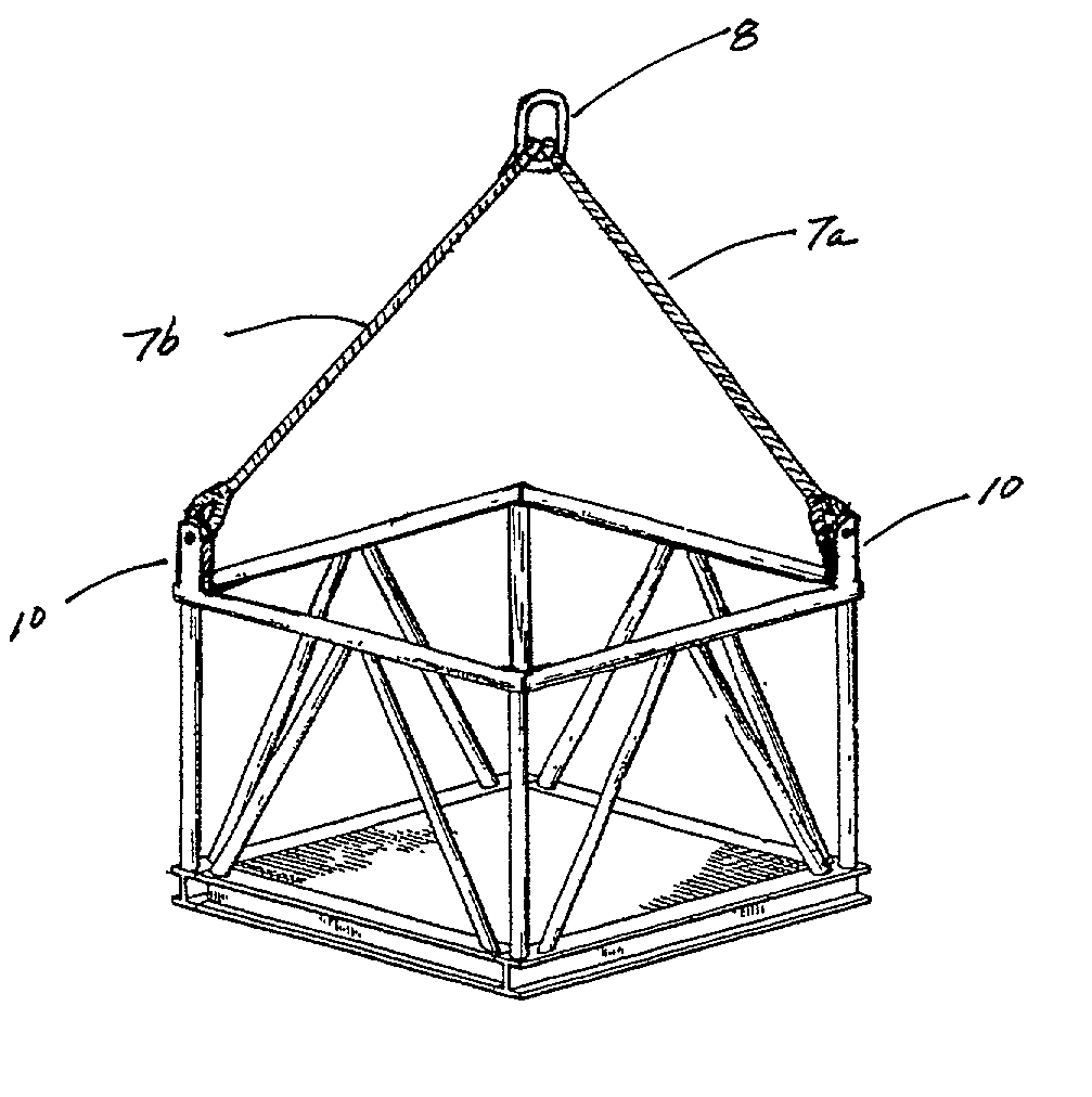
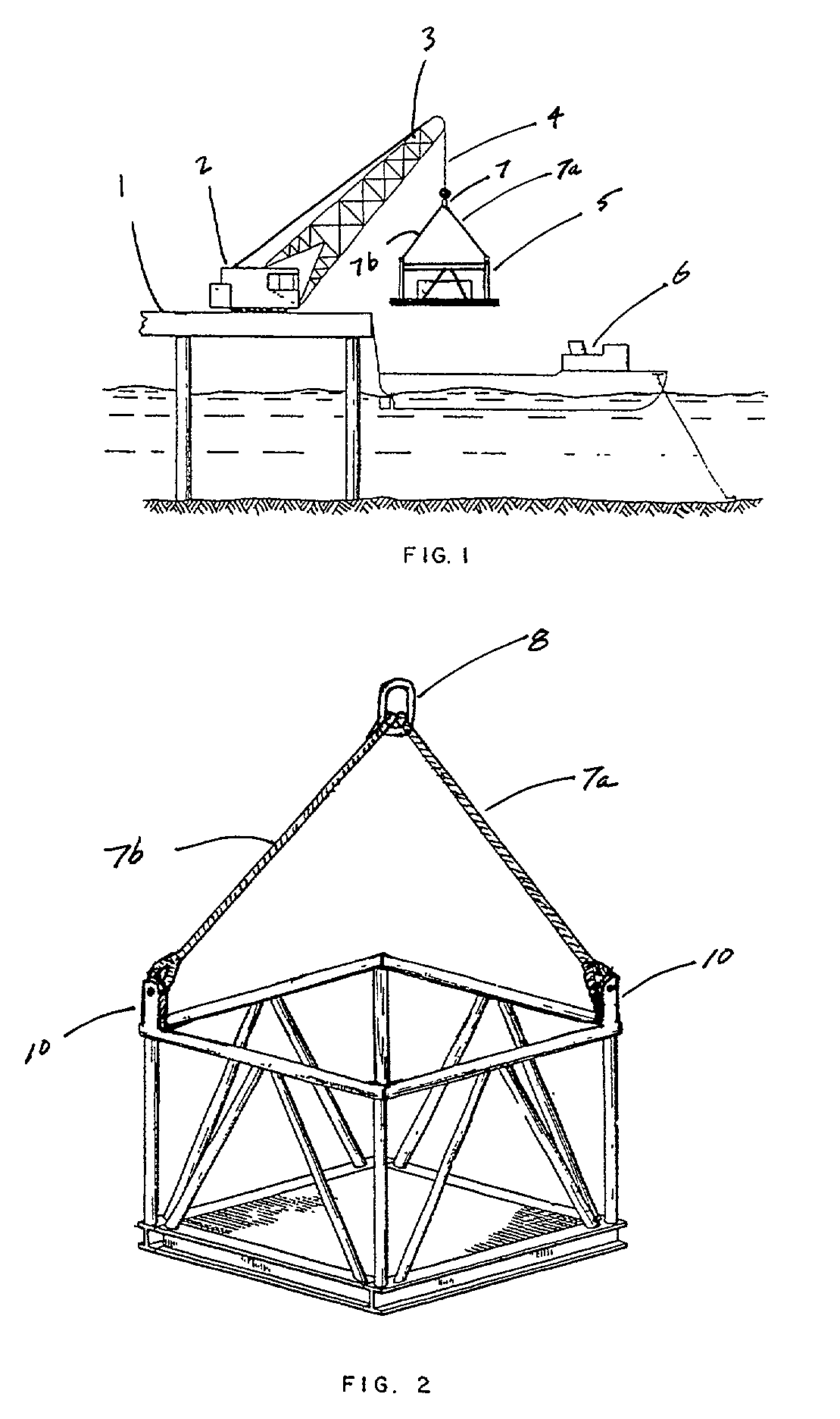
[0022] Referring to the drawings, FIG. 1 depicts a diagrammatic view of equipment being loaded from an offshore platform to a waiting boat using a crane. Platform 1 provides a foundation for crane 2, having boom 3 and line 4. Basket 5 is depicted as being lowered onto waiting boat 6 using crane 2. Slings 7 are used to connect line 4 of crane 2 to basket 5. Slings 7 utilize multiple lines 7a and 7b, to evenly distribute the weight of basket 5, and provide stability during the lift and transfer of basket 5. It is well known in the prior art to utilize pad-eyes, welded or otherwise attached to a load such as basket 5, to provide connection means for attaching lines 7a and 7b of sling 7 to basket 5. The integrated lifting means of the present invention eliminates the need for such pad-eyes, and the problems associated with same.

[0023] FIG. 2 depicts basket 5 equipped with the integrated lifting apparatus 10 of the present invention; to improve stability of the load during the lift, bas...


PUM


Abstract

An integrated lifting apparatus for attaching a sling or other lifting means to a load having an upright and substantially hollow post. A bore is provided near the upper extent of such hollow post, said bore extending horizontally through said hollow post. A threaded bolt having an enlarged head on one end, preferably constructed of high strength and/or shear resistant material, is disposed through said bore. A lock nut having an outer diameter greater than the diameter of said bore is threaded onto the end of said bolt. If desired, a cotter pin can also be used to secure such lock nut on said bolt.

Description

[0001] NONESTATEMENTS AS TO RIGHTS TO INVENTIONS MADE UNDER FEDERALLY SPONSORED RESEARCH AND DEVELOPMENT[0002] NONE[0003] 1. Field of the Invention[0004] The present invention relates to a lifting apparatus which can be used in connection with a crane or hoist for the loading or unloading of cargo. More specifically, the present invention relates to a lifting apparatus which improves the strength characteristics of pallets, baskets and other structures used for containing or supporting loads being lifted, while eliminating the need for welded pad-eyes, loops or similar structures.[0005] 2. Description of the Related Art[0006] Numerous arrangements have been devised for the purpose of lifting large production skids or similar equipment so that they may be transported from one location, such as on board a boat, to another location, such as an offshore platform using a crane, hoist or other lifting means. In the course of such transport activities, consideration must be given to the ma...

Claims


Application Information

Patent Timeline
Patent Type & Authority Applications(United States)
IPC IPC(8): B66C1/16
CPCB66C1/16
Inventor SEGURA, VICTOR JOSEPH
Owner SEGURA VICTOR JOSEPH
Why Eureka
Try Eureka