
Latch apparatus for portable electronic devices

a technology for electronic devices and latches, which is applied in the direction of electrical apparatus casings/cabinets/drawers, instruments, navigation instruments, etc., can solve the problems of initial bulkiness of systems and easy shock and vibration

Inactive Publication Date: 2008-01-24
ALPINE ELECTRONICS INC
View PDF21 Cites 8 Cited by
  • Summary
  • Abstract
  • Description
  • Claims
  • Application Information

AI Technical Summary

Benefits of technology

[0007] It is, therefore, an object of the present invention to provide a latch apparatus that can securely mount a display device to a device mount.
[0008] It is another object of the present invention to provide a latch apparatus which is able to sufficiently withstand the forces that derive from the vehicle's vibrations and shocks while allowing easy detachment as needed.
[0010] In at least one embodiment, the latch apparatus includes a pin with a ramp that can make contact to a ramp of an actuator, which allow the display device to be easily secured into the device mount by a simple sliding action, but which securely holds the display device and prevents any unintentional separation of the display device from the device mount. The latch apparatus further has a retractable pin or pins which so secure the display device in the device mount and which can be retracted by a simple operation of a user to allow the display device to be removed from the device mount.
[0011] In such embodiments, the latch apparatus may operate with a stopper that is positioned on the device mount, where the stopper prevents the reception of the display device into the device mount when the navigation antenna is in its non-operational position. The pin is biased to one direction such that the pin secures the display device in a normal condition. The pin can be moved to the direction opposite to the biased direction by applying a certain amount of force to the actuator.
[0013] Thus, the latch apparatus can securely mount the display device to the device mount and sufficiently withstands the forces that derive from the vehicle's vibrations and shocks while allowing easy detachment as needed. Further, the device mount is fit to the vehicle to receive the portable display device therein such that the navigation antenna of the portable display device is in the operational condition when the portable display device is securely fixed to the device mount.

Problems solved by technology

Because of data storage requirements, such systems were initially somewhat bulky and required that the systems be permanently installed in the vehicle.
A vehicle sometimes must pass through a bumpy road and can be susceptible to shocks and vibrations due to the road condition.

Method used


Image

  • Latch apparatus for portable electronic devices
  • Latch apparatus for portable electronic devices
  • Latch apparatus for portable electronic devices

Examples


Embodiment Construction

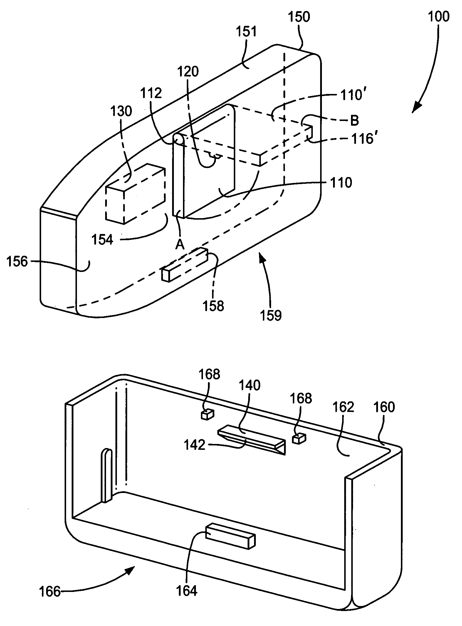
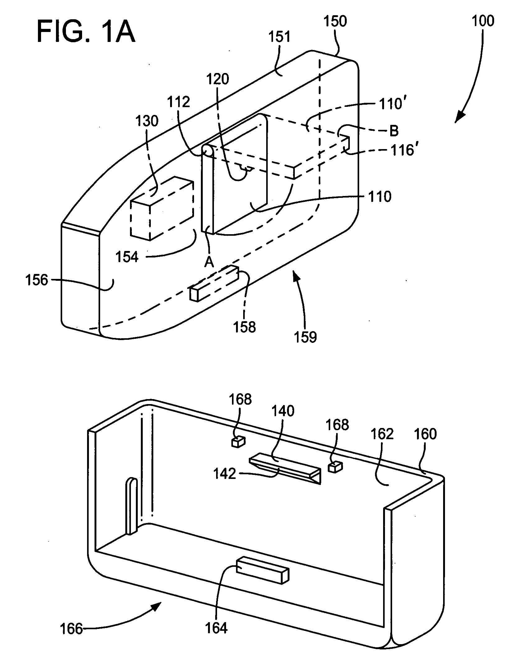
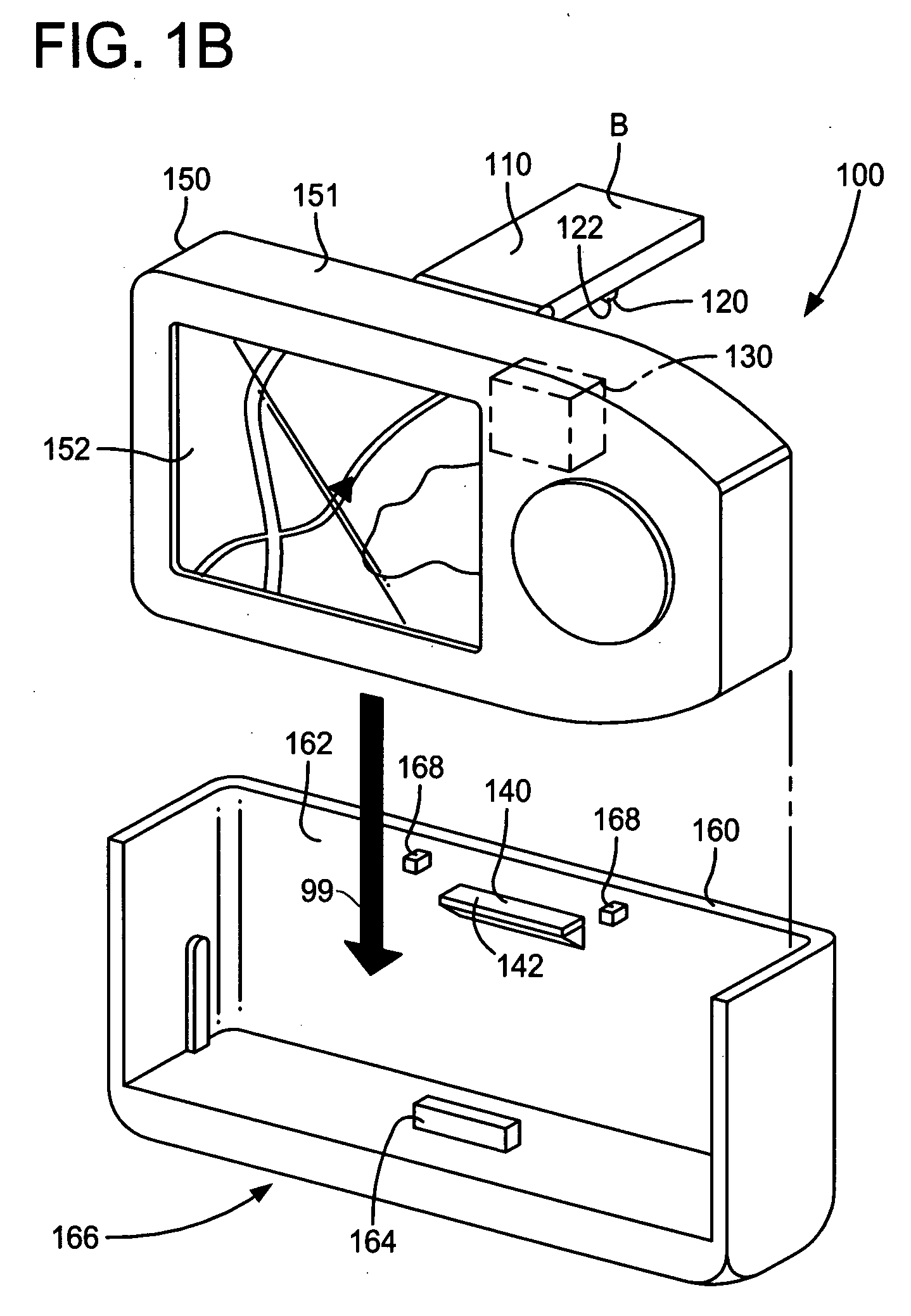
[0025] As shown in FIGS. 1A and 1B, in at least one embodiment, a display control apparatus 100 mainly comprises a display device 150 and a device mount or cradle 160. The display device 150 is a portable device that is capable of displaying an image on its screen and generating audible sounds as well as receiving signals by means of a GPS antenna as will be explained further in detail. The device mount (cradle) 160 is designed to receive the display device 150 and establish electrical connection therebetween. The display device 150 includes a navigation (GPS) antenna 110, an antenna positioning sensor 120, a device function controller 130 and a stopper 140.

[0026] The display device 150 can, depending on the embodiment, be any of a variety of devices. For example, the display device 150 can be a portable navigation and video display device, having a screen 152 which can display navigation or non-navigational related images, as shown in FIG. 1B. In this example, the screen 152 shows...


PUM


Abstract

The latch apparatus for portable display devices has a pin portion and an actuator. The latch apparatus has an opening into which the pin portion is inserted to secure the display device in a device mount. The actuator applies force to release the pin to remove the display device from the device mount. Both the actuator and the pin portion have ramps that are designed to make contact with each other and slide as force is exerted to the actuator. Due to the ramps, the pin portion moves to withdraw from the opening of the display device as force is applied to the actuator. Biasing means maintains the position of the pin such that the pin portion securely holds the display device in the device mount unless the actuator is pressed for releasing the pin portion.

Description

[0001] This application claims the benefit of U.S. Provisional Application No. 60 / 754,240 filed Dec. 27, 2005.FIELD OF THE INVENTION [0002] This invention relates generally to a latch apparatus for a portable electronic device, and more particularly, to a latch apparatus having an actuator portion and a pin portion where the pin portion is biased to fit into an opening to securely fix the portable electronic device to a device mount. BACKGROUND OF THE INVENTION [0003] A navigation system performs travel guidance for enabling a user to easily and quickly reach the selected destination. A typical example is a vehicle navigation system where a vehicle is equipped with a navigation function to guide a driver to a destination through a calculated route. In recent years, the use of both mobile media and navigation systems in a vehicle has become increasingly more common. Because of data storage requirements, such systems were initially somewhat bulky and required that the systems be perma...

Claims


Application Information

Patent Timeline
Patent Type & Authority Applications(United States)
IPC IPC(8): H05K7/00G01C21/00
CPCG01C21/26G01C21/265H05K5/0204
Inventor DIAZ, MELVIN
Owner ALPINE ELECTRONICS INC
Learn More