Temperature-independent measurements of gas concentration

a technology of temperature and gas concentration, applied in the direction of optical radiation measurement, distance measurement, instruments, etc., can solve the problems of inability or difficulty in inability to achieve the temperature and gas composition data required by prior art methods to correct for linestrength and linewidth, and inability to achieve or achieve gas composition and/or temperature measurement. , the distribution of temperature and composition along the optical beam path is not uniform and unknown

Inactive Publication Date: 2002-09-26
THE BOARD OF TRUSTEES OF THE LELAND STANFORD JUNIOR UNIV
View PDF0 Cites 5 Cited by
  • Summary
  • Abstract
  • Description
  • Claims
  • Application Information

AI Technical Summary

Problems solved by technology

Unfortunately, in many situations the temperature and gas composition data required by prior art methods to correct for linestrength and linewidth is unknown.
In other cases, gas composition and/or temperature measurements are not feasible or difficult.
In the example of on-road remote sensing of vehicle exhausts, the temperature and composition distributions along the optical beam path are non-uniform and unknown.
Similar problems are encountered in monitoring emissions from stacks, especiall

Method used


Image

  • Temperature-independent measurements of gas concentration
  • Temperature-independent measurements of gas concentration
  • Temperature-independent measurements of gas concentration

Examples


Embodiment Construction

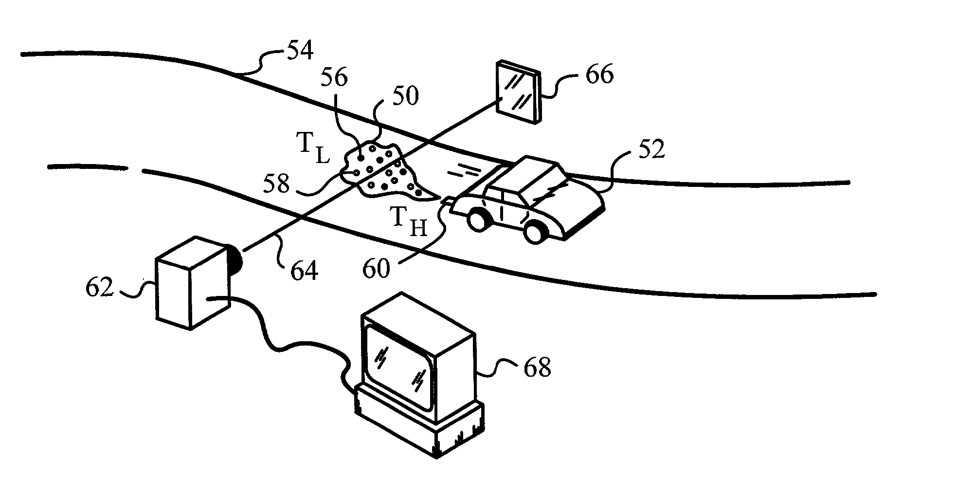
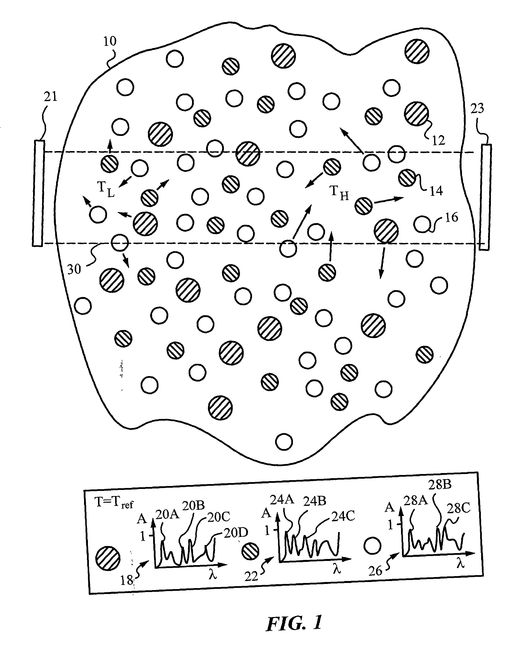
[0031] The invention will be best understood by initially referring to the schematic diagram of FIG. 1 illustrating a sample 10 of three gases 12, 14, 16. Sample 10 may contain additional gases which are not shown for reasons of clarity. Sample 10 can be located in a closed container or it can be an open sample, e.g., it can be a volume of arbitrary shape and not confined by any container. For example, gases 12, 14, 16 can be unconstrained gases found in the ambient atmosphere.

[0032] It is despaired to determine the concentration of gas 12 in sample 10. In other words, gas 12 is selected as a probe gas. It is well known that at a specific or constant temperature probe gas 12 has a certain spectrum 18 for electromagnetic radiation, specifically the optical portion of the radiation spectrum. Spectrum 18 indicates percent absorption A along the y-axis and from this spectrum it can be seen that probe gas has several absorption peaks. In the present case a reference temperature T.sub.ref...


PUM


Abstract

A method and apparatus for temperature-independent determination of a concentration of a probe gas in a sample over a selected temperature range between a low temperature TL corresponding to a lowest temperature expected or found in the sample and a high temperature TH corresponding to a highest temperature expected or found in the sample. In accordance with the method, a probe temperature function of the probe gas is determined over the temperature range using a first spectroscopic technique. Then, a second spectroscopic technique is selected, a reference gas is identified and a reference temperature function of the reference gas is determined using the second spectroscopic technique over the temperature range. In particular, the reference gas is identified such that a ratio of the probe temperature function and the reference temperature function is substantially constant over the temperature range. A probe reaction of the probe gas and a reference reaction of the reference gas is then measured by the first and second spectroscopic techniques and the concentration of the probe gas is derived from the probe reaction and reference reaction. The method of the invention can be take advantage of spectroscopic techniques such as absorption spectroscopy employing a test beam of light at several wavelengths with at least one wavelength for either probe transition or reference transition. The method and apparatus can be used in monitoring various gas samples and are especially well-suited for determining probe gas concentrations in samples which exhibit non-uniformities in temperature, pressure and gas composition, e.g., as encountered in vehicle exhaust samples.

Description

[0001] This application claims priority from U.S. Provisional Patent Application No. 60 / 249,522, filed on Nov. 17, 2000 and which is herein incorporated by reference.[0003] This invention relates generally to using spectroscopic techniques for gas concentration measurements, and in particular to using a ratio of gas concentrations to obtain temperature-independent measurements.BACKGROUND AND PRIOR ART[0004] Gas concentrations are measured in laboratory experiments, industrial plant operations as well as monitoring and sensing in public or private areas. In some of these cases the measurements are performed to determine what chemical reactions are taking place, in others they represent direct results, e.g., concentrations of pollutants in the atmosphere such as exhausts from stack and vehicles (smog check and on-road remote sensing).[0005] Gas concentration sensors based on spectroscopic techniques and absorption spectroscopy in particular have been widely used for many industrial ap...

Claims


Application Information

Patent Timeline
IPC IPC(8): G01J3/42G01J5/60G01N21/35
CPCG01J3/42G01J5/60G01N21/3504G01N2021/1793G01N2201/1211G01N2021/3513
Inventor WANG, JIANHANSON, RONALD K.
Owner THE BOARD OF TRUSTEES OF THE LELAND STANFORD JUNIOR UNIV
Why Eureka
Try Eureka