Cortical bone cervical Smith-Robinson fusion implant

Inactive Publication Date: 2002-09-26
RTI BIOLOGICS INC
View PDF6 Cites 84 Cited by
  • Summary
  • Abstract
  • Description
  • Claims
  • Application Information

AI Technical Summary

Problems solved by technology

However, in a recent study evaluating the success and relief rates achieved according to these procedures, it was found that less than 100% success

Method used


Image

  • Cortical bone cervical Smith-Robinson fusion implant
  • Cortical bone cervical Smith-Robinson fusion implant
  • Cortical bone cervical Smith-Robinson fusion implant

Examples


Embodiment Construction

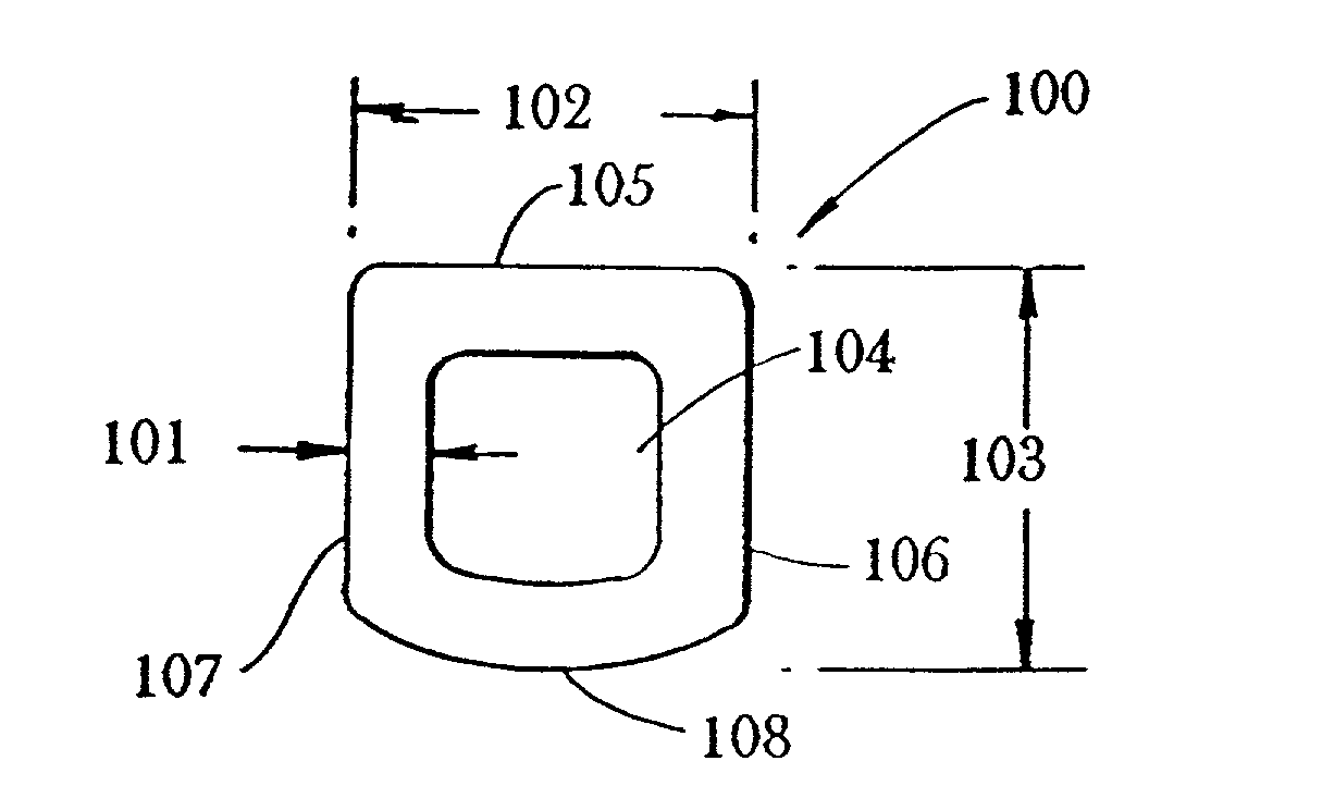
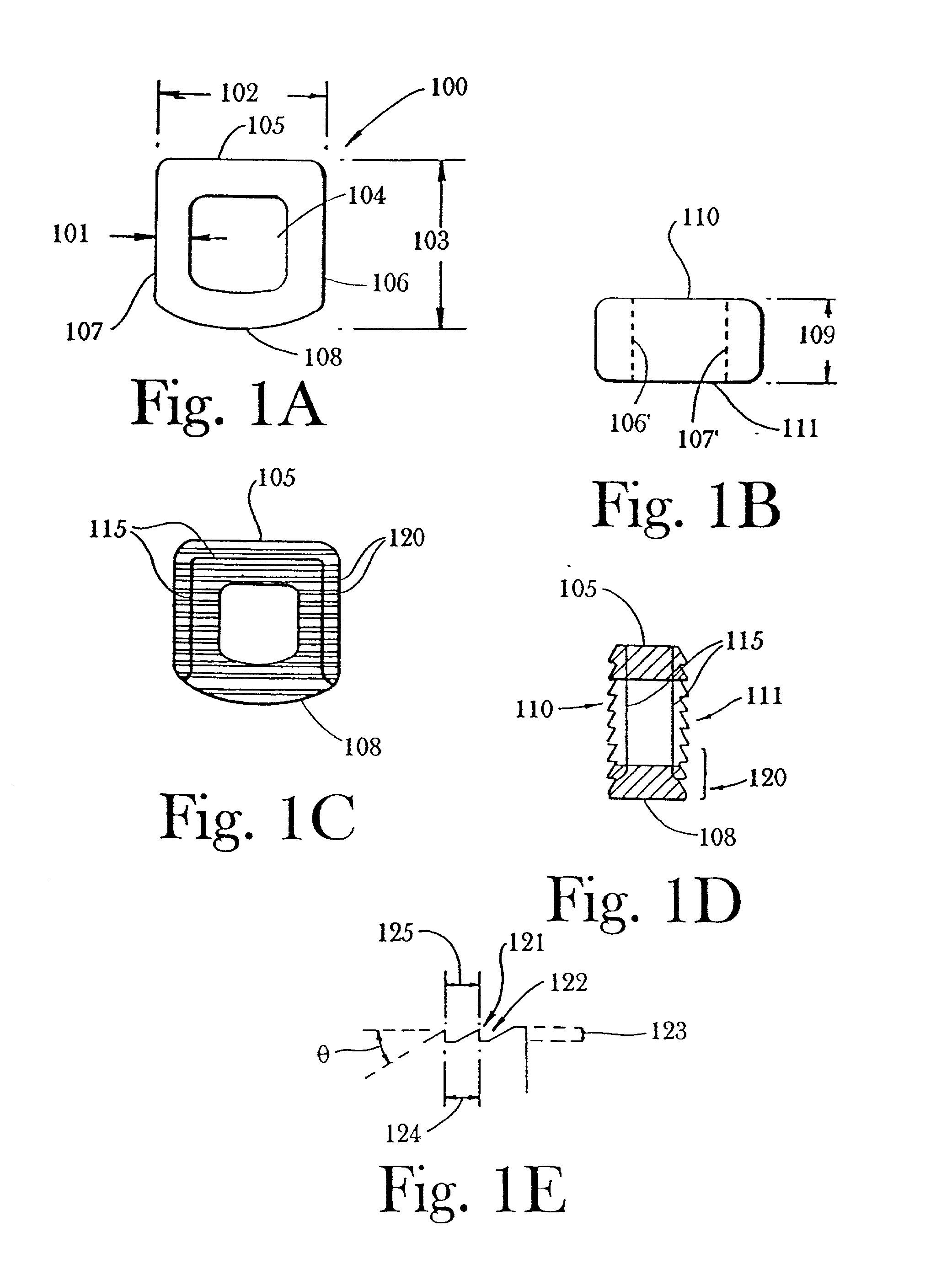
[0023] According to this invention, a substantially "D"-shaped cortical bone implant for cervical Smith-Robinson fusions is produced, preferably under aseptic conditions. Class 10 clean room processing is desirable, and sterilization of all machining tools is likewise preferred, (particularly after switching from one allograft donor to the next), so that the finished product may be treated by standard techniques known in the art (alcohol, peroxide, or like treatments), prior to storage and shipment to physicians for use in implantation procedures. Because of the peculiarities of working with bone, and in particular, because of the desirability of maintaining aseptic conditions while working with this material, novel approaches have been adopted in the production of the product of this invention.

[0024] The implant is preferably formed from cortical bone obtained from tibia, femur or other source of strong cortical bone. The bone source may be autograft or, due to possible complicatio...


PUM


Abstract

An implant composed substantially of cortical bone is provided for use in cervical Smith-Robinson vertebral fusion procedures. The implant is derived from allograft or autograft cortical bone sources, is machined to form a symmetrically or asymmetrically shaped (e.g. a substantially "D"-shaped) implant having a canal running therethrough according to methods of this invention, and inserted into the space between adjacent cervical vertebrae to provide support and induce fusion of the adjacent vertebrae. Osteogenic, osteoinductive or osteoconductive materials may be packed into the canal of the implant to expedite vertebral fusion and to allow autologous bony ingrowth.

Description

CROSSREFERENCE TO RELATED APPLICATIONS[0001] This application is a continuation of currently pending application Ser. No. 09 / 701,933, filed Aug. 25, 1998, which is a continuation-in-part of currently pending application Ser. No. 08 / 920,630 filed Aug. 30, 1997, to which Applicants claim the benefit of priority under 35 USC .sctn.120.1.0 BACKGROUND OF THE INVENTION[0002] 1.1 Field of the Invention[0003] This invention relates to a cortical bone implant for use in cervical Smith-Robinson vertebral fusion procedures, as well as methods for the manufacture and use thereof. Furthermore, this application relates to an assembled implant comprised of two or more individual segments fastened together.[0004] 1.2 Background Art[0005] Since at least the mid to late 1950's anterior cervical spinal fusions have been performed in order to alleviate chronic neck, arm and shoulder pain caused by trauma, disc herniation, or spondylosis (Robinson and Smith, 1955; Smith and Robinson, 1958). The classic ...

Claims


Application Information

Patent Timeline
IPC IPC(8): A61F2/00A61F2/28A61F2/30A61F2/44A61F2/46
CPCA61F2/3094A61F2/442A61F2/4455A61F2/4644A61F2002/2817A61F2002/2825A61F2002/2835A61F2002/2839A61F2002/2892A61F2002/30057A61F2002/30187A61F2002/30403A61F2002/30551A61F2002/30599A61F2002/30828A61F2002/30879A61F2002/30904A61F2002/30975A61F2002/4475A61F2002/448A61F2002/4649A61F2220/0025A61F2230/0034A61F2250/0063A61F2310/00293A61F2002/3055A61F2002/30593
Inventor GROOMS, JAMIE M.CARTER, KEVIN C.SANDER, TOMDULEBOHN, DAVID H.
Owner RTI BIOLOGICS INC
Why Eureka
Try Eureka