
Take-up and release mechanism for a printer

Inactive Publication Date: 2002-10-03
ZIH CORP
View PDF6 Cites 0 Cited by
  • Summary
  • Abstract
  • Description
  • Claims
  • Application Information

AI Technical Summary

Benefits of technology

[0006] Another object of the present invention is to provide a mechanism for a printer which prevents the windings of backing from slipping off of the mechanism.
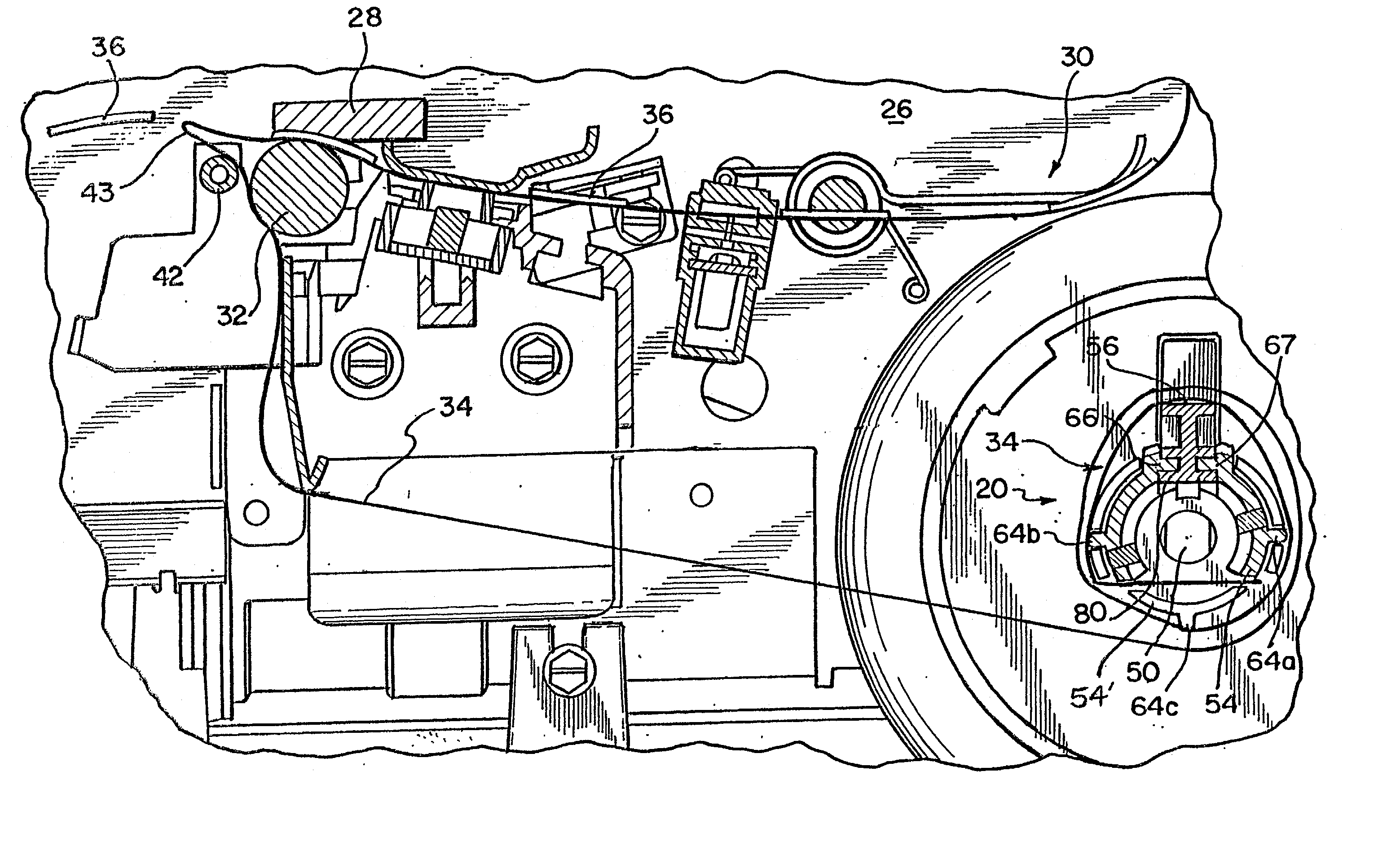
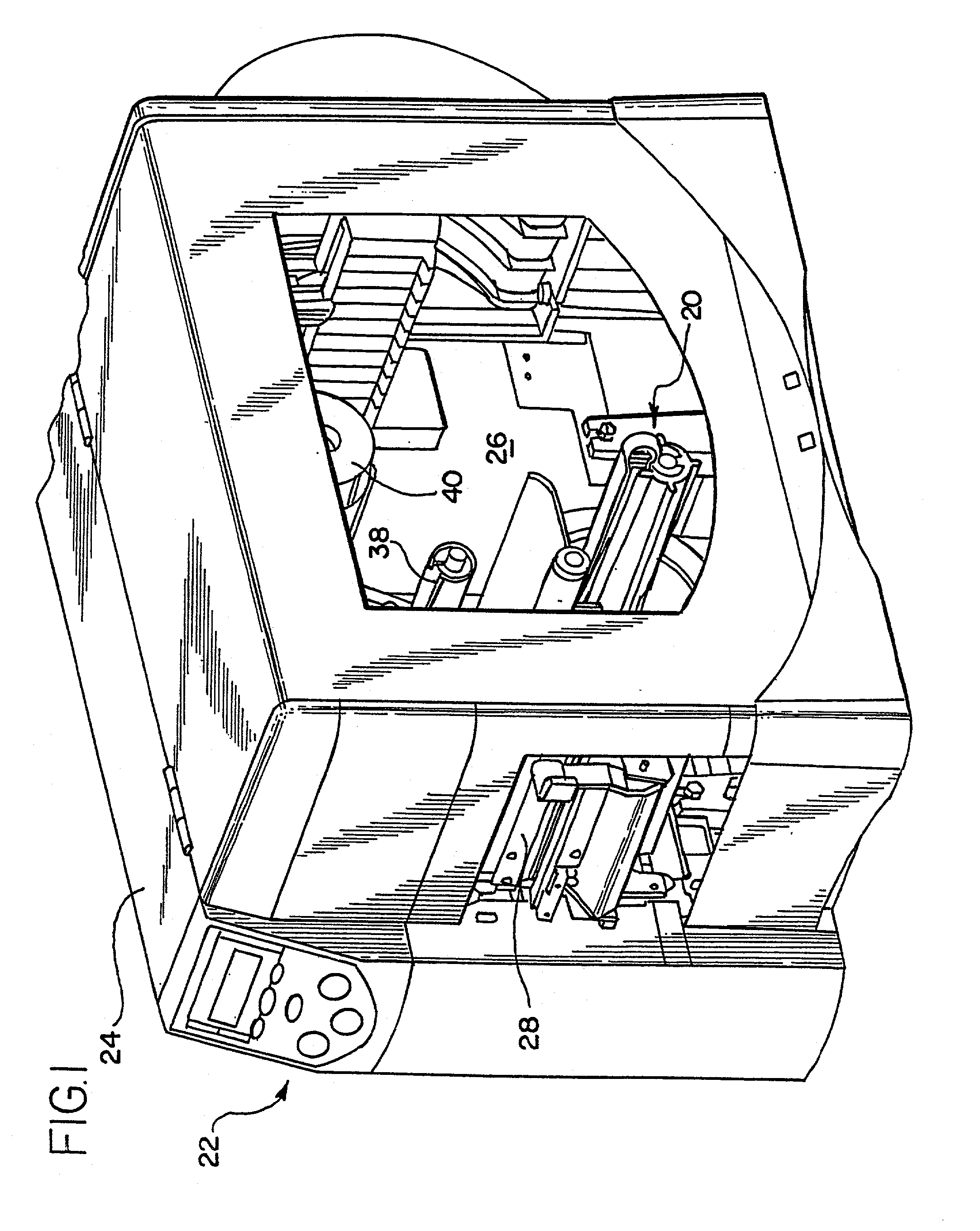
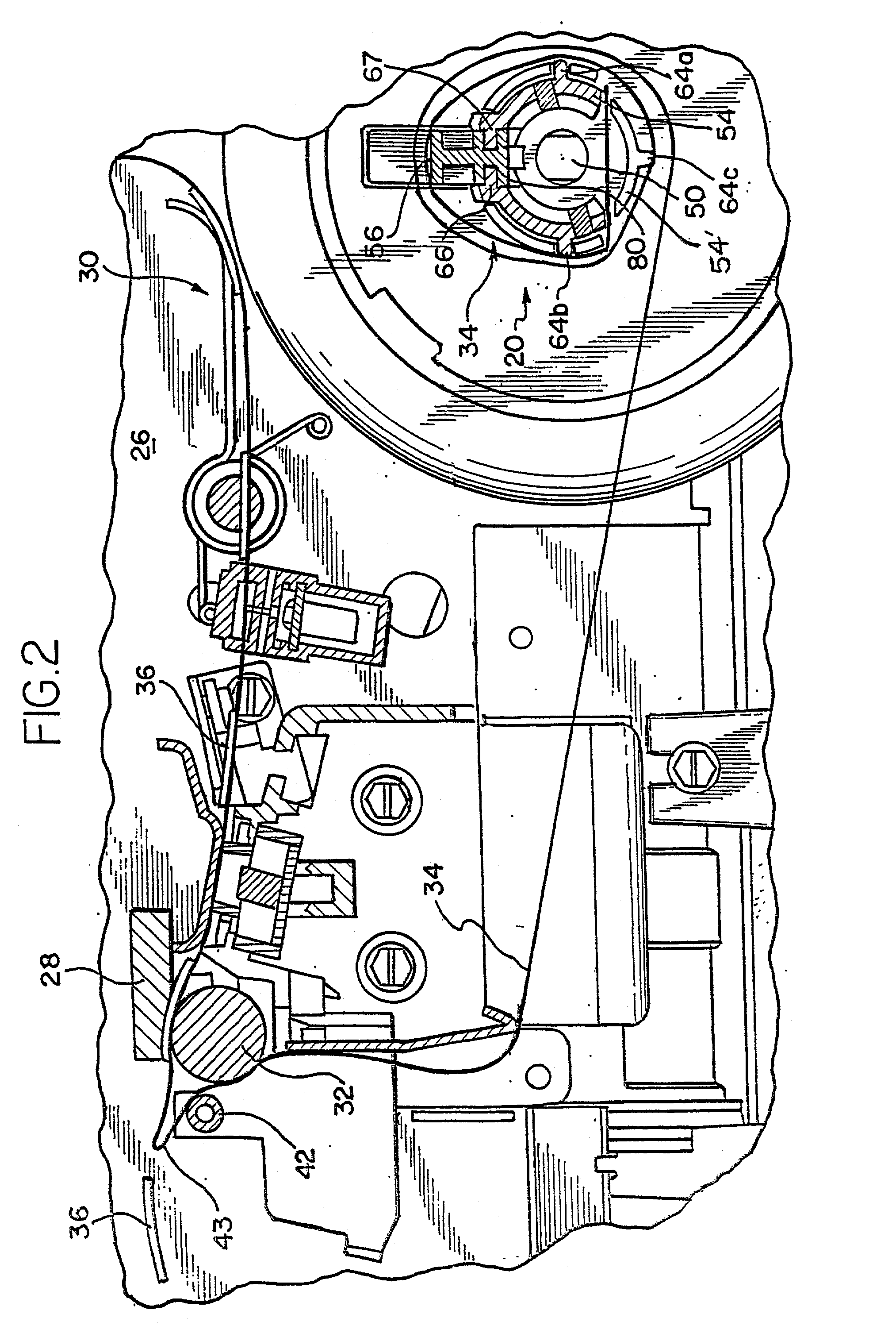
[0008] Briefly, and in accordance with the foregoing, a media take-up and release mechanism includes a take-up spindle mounted to a printer. The take-up spindle is used to collect windings of the backing. A fin is engaged with the take-up spindle. A ramp is provided on the exterior surface of the take-up spindle and fingers extend from the take-up spindle on either side of the ramp. An inner surface of the fin is sloped at an angle which corresponds with the angle of the ramp. A locking protrusion extends from the inner surface of the fin and is capable of sliding along the ramp. The locking protrusion is positioned between the fingers and engages the fin with the spindle. A spring provides biasing between the fin and the back plate. Winding of the backing begins by placing the backing through a slit in the spindle. The backing is then wound around the perimeter of the spindle and the fin. When the backing is to be released, the user grasps the fin and pulls the fin away from the backplate, causing the spring to extend. As the spring is pulled away from the backplate, the fin slides along the ramp causing the effective diameter around which the inner windings of the backing are wound to decrease. Because the effective diameter around which the inner windings are wound is decreased, a space is provided between the take-up spindle and fin and the inner windings and therefore the backing can be easily removed from the take-up spindle.

Problems solved by technology

Also, in a prior art printer, when a take-up spindle is used to collect the backing, the inner windings of the backing become tightly wound around the take-up spindle and it is difficult to remove the backing from the take-up spindle.
In addition to the windings being tightly wound around the take-up spindle, the windings are often positioned close to a back plate against which the take-up spindle sits making it difficult for a users to place his fingers behind the windings to assist in removing the backing from the take-up spindle.

Method used


Image

  • Take-up and release mechanism for a printer
  • Take-up and release mechanism for a printer
  • Take-up and release mechanism for a printer

Examples


Embodiment Construction

[0015] While the invention may be susceptible to embodiment in different forms, there is shown in the drawings, and herein will be described in detail, a specific embodiment with the understanding that the present disclosure is to be considered an exemplification of the principles of the invention, and is not intended to limit the invention to that as illustrated and described herein.

[0016] A take-up and release mechanism 20 is provided for a printer 22. The mechanism 20 can be used in connection with a variety of devices in which a continuous medium is to be collected. The mechanism 20 is shown in FIGS. 1 and 2 in connection with a thermal demand printer 22, but it is to be understood that the present invention can be used on other types of printers. The mechanism 20 is shown in connection with media 30, which is formed from a continuous backing 34 (also known as a liner or a web) having a plurality of labels 36 releasably secured thereto. The labels 36 are releasably secured to th...


PUM


Abstract

A media take-up and release mechanism includes a spindle and a fin. A ramp is provided on the exterior of the spindle. A fin engages the ramp on the spindle. Backing is collected by winding the backing around the take-up spindle assembly. To remove a roll of backing from the take-up spindle assembly, the effective diameter of the take-up spindle assembly is reduced by sliding the fin along the ramp. With the effective diameter of the take-up spindle assembly reduced, the backing slides easily over and off of the take-up spindle assembly.

Description

[0001] This application claims the priority of U.S. provisional application Serial No. 60 / 279,186 filed on Mar. 27, 2001 and entitled "Liner Take-Up Spindle For A Printer".[0002] A mechanism for a printer is provided which collects a backing and removes the backing from a take-up spindle. For example, the mechanism can be used in connection with a printer which includes a peel assembly.[0003] Printers having peel assemblies are used to print on labels which are attached to a backing. After printing, the labels are peeled from the backing using a peel mechanism. After peeling, the backing is collected and disposed of. Sometimes, the backing is simply allowed to exit the printing and peeling assembly where it is then collected and disposed of. Alternatively, the backing is wound on a take-up spindle. Once the take-up spindle is full, the backing is removed from the spindle and disposed of.[0004] In prior art printer, a take-up spindle is used to collect the backing, the diameter of th...

Claims


Application Information

Patent Timeline
IPC IPC(8): B65H18/02B65H19/30B65H75/24
CPCB65H18/026B65H2405/451B65H75/242B65H19/30B65H75/2484
Inventor WATKINS, DANE
Owner ZIH CORP
Learn More