Method and apparatus for high speed digitized exposure

a digital exposure and high-speed technology, applied in the field of image projection, image scanning and image printing systems, can solve the problems of reducing the resolution of printed images, reducing the quality of projected images, and limiting the resolution of images

Inactive Publication Date: 2002-10-03
KUBOTA MASANORI
View PDF0 Cites 26 Cited by
  • Summary
  • Abstract
  • Description
  • Claims
  • Application Information

AI Technical Summary

Problems solved by technology

The resolution and pitch of the light valves typically determines the resolution and pitch limitations of the image.
Large gaps reduce the quality of projected images and reduce the resolution of the printed image.
Current light valve technology is not able to meet this requirement without costly optical realignment.
Changing the resolution available with a light valve currently requires the expensive variable optics and time consuming adjustments in the projector, imager, or detector.

Method used


Image

  • Method and apparatus for high speed digitized exposure
  • Method and apparatus for high speed digitized exposure
  • Method and apparatus for high speed digitized exposure

Examples


Embodiment Construction

)

[0022] The invention will next be illustrated with reference to the figures wherein similar numbers indicate the same elements in all figures. Such figures are intended to be illustrative rather than limiting and are included herewith to facilitate the explanation of the apparatus of the present invention.

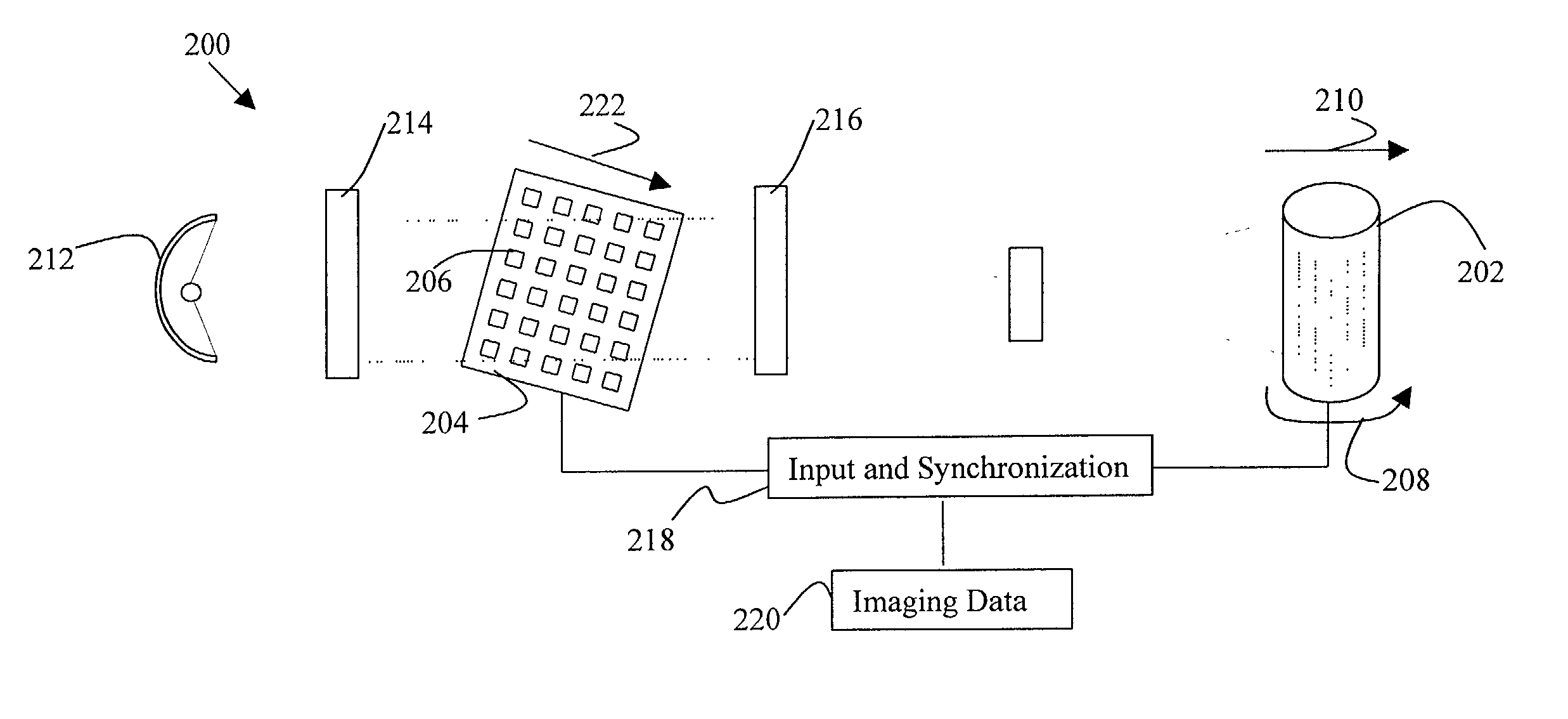
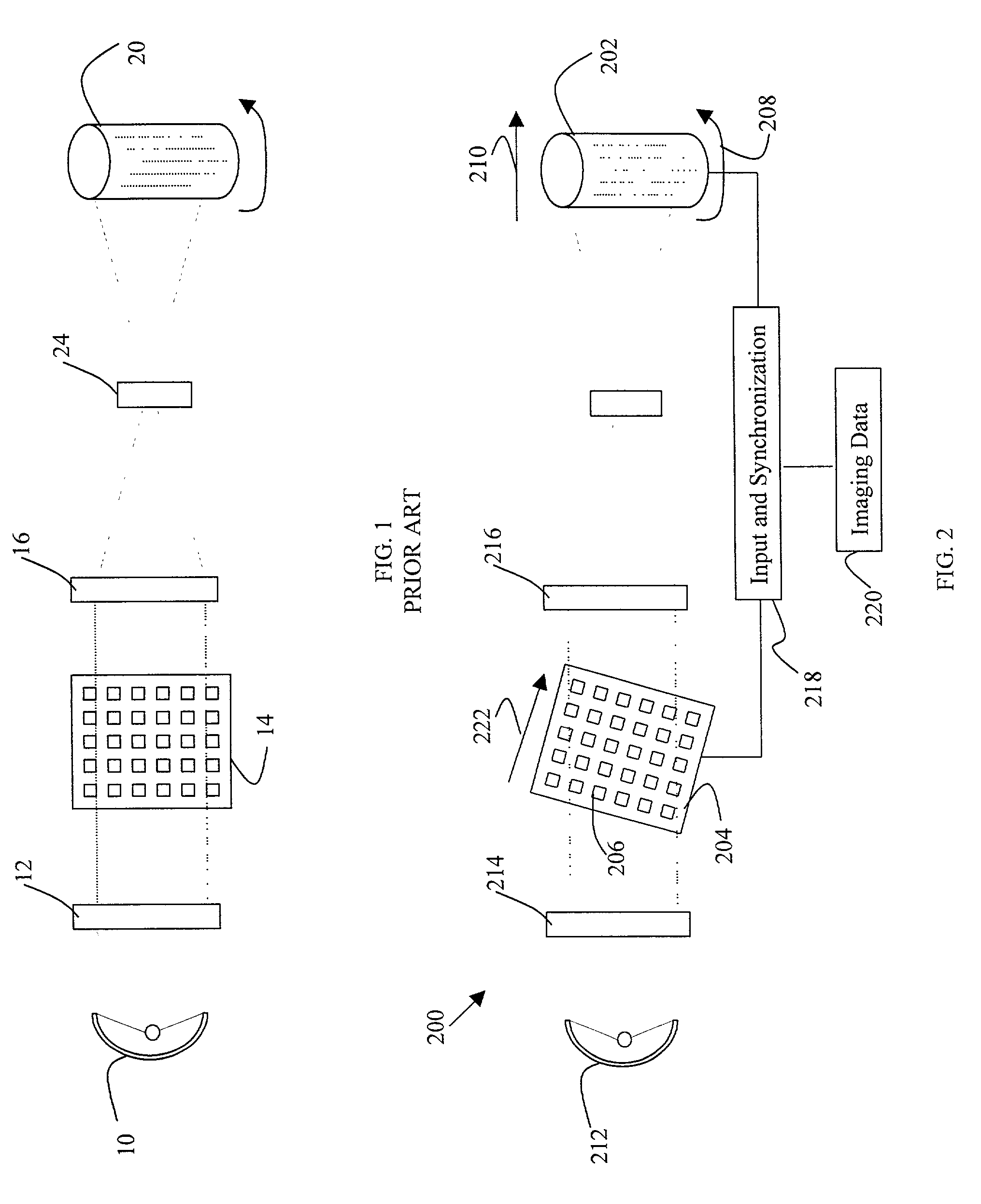
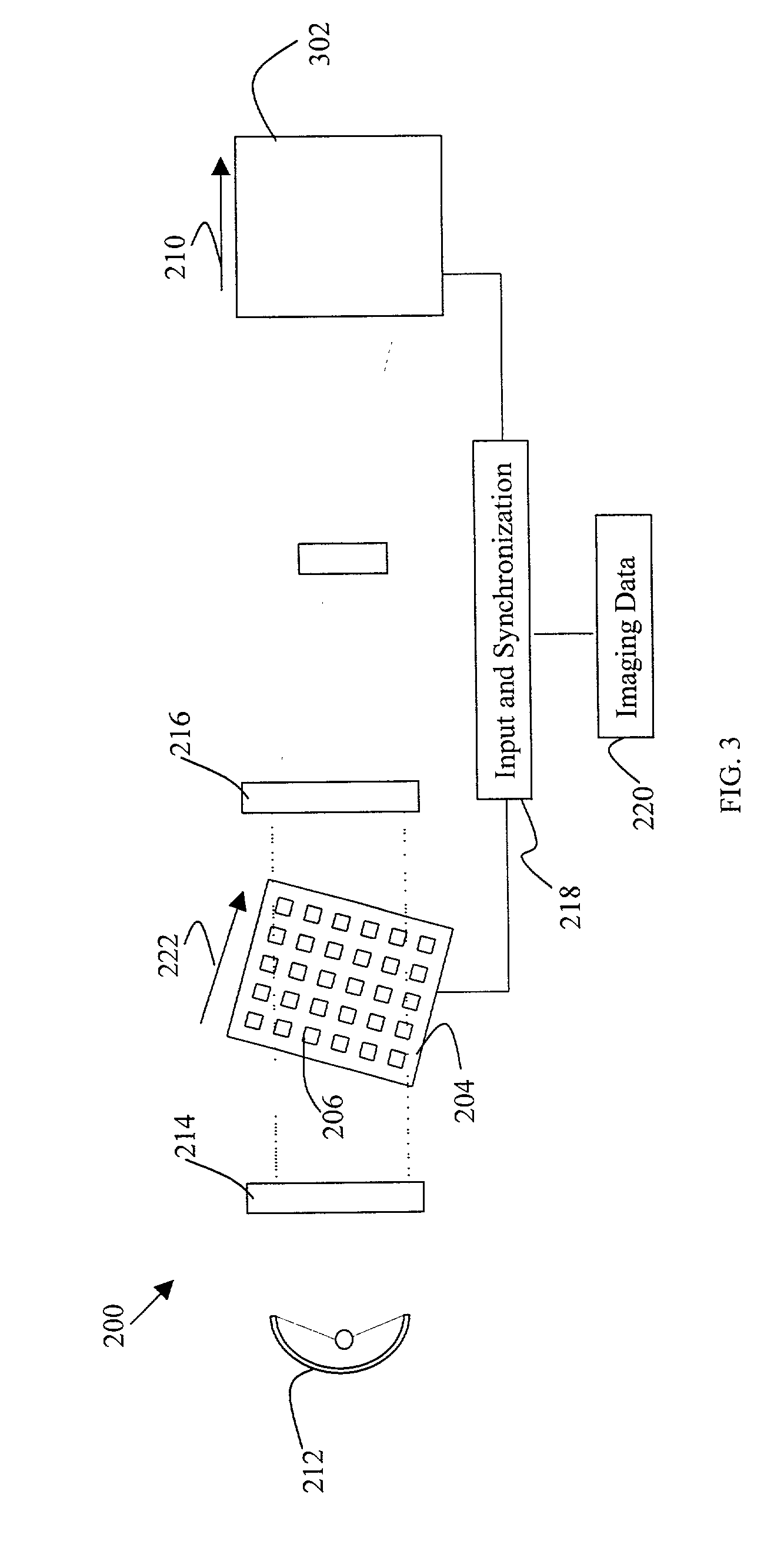
[0023] One embodiment of the present invention is schematically illustrated in FIG. 2 and includes an imaging system 200 comprising a surface for receiving an image 202, and a light modulator 204 comprising a plurality of light valves 206 in a two-dimensional array having orthogonal rows and columns. The rows and columns of the array are aligned in a Cartesian coordinate system with two orthogonal axes. For description purposes herein the array columns are described as being aligned on the first axis and the array rows are described as being aligned along the second axis in this Cartesian coordinate system.

[0024] As shown in FIG. 2, a radiant energy source 212 and a lens 214 direc...


PUM


Abstract

A light modulation and exposure system comprising: a light source; a light sensitive media; a two-dimensional light modulator containing a plurality of rows of light valves; means of imaging light source onto light modulator and light modulator onto light sensitive material; means of generating relative motion between image of light modulator and light sensitive material; means of shifting into the first of rows the data to be imaged onto light sensitive material and means of editing data from the first row to subsequent rows of modulator at a rate keeping the image of individual data pattern substantially stationary relative to light sensitive material until data transferred to the selected final rows; this sequence continuing until all data to be imaged has passed through light modulator. The two-dimensional light modulator may be oriented at a rotation relative to the direction of motion of the light sensitive media in a manner conducive to achieving variable resolution levels and half-tone generation.

Description

[0001] This application claims priority to U.S. Provisional Application No. 60 / 279,822 filed Mar. 29, 2001, the contents of which are incorporated herein by reference.[0002] 1. Field of the Invention[0003] The present invention relates generally to image projection, image scanning and image printing systems and more particularly to a method of controlling resolution and exposure to improve image quality using imaging array technology.[0004] 2. Background of the Invention[0005] Light valves, such as micro-electro-mechanical systems (MEMS) and liquid crystal displays (LCD), have been used in image exposure processes to expose light sensitive media in patterns prescribed by rows and columns of the light valve modules. Typically, the desired image is defined by light valve modules activated to illuminate the light sensitive media directly. The resolution and pitch of the light valves typically determines the resolution and pitch limitations of the image.[0006] FIG. 1, adapted from U.S. ...

Claims


Application Information

Patent Timeline
Patent Type & Authority Applications(United States)
IPC IPC(8): B41J2/465
CPCB41J2/465
Inventor KUBOTA, MASANORI
Owner KUBOTA MASANORI
Why Eureka
Try Eureka