Exerciser for the muscles of pelvic floor

a technology for strengthening the muscles of the pelvis and pelvis, which is applied in the direction of non-surgical orthopedic devices, resilient force resistors, surgery, etc., can solve the problems of weakening or damage to the lower pelvis muscles

Inactive Publication Date: 2002-10-03
UI
View PDF4 Cites 18 Cited by
  • Summary
  • Abstract
  • Description
  • Claims
  • Application Information

AI Technical Summary

Problems solved by technology

The lower pelvic muscles may become damaged or weakened through childbirth, lack of use, age or other reasons.

Method used


Image

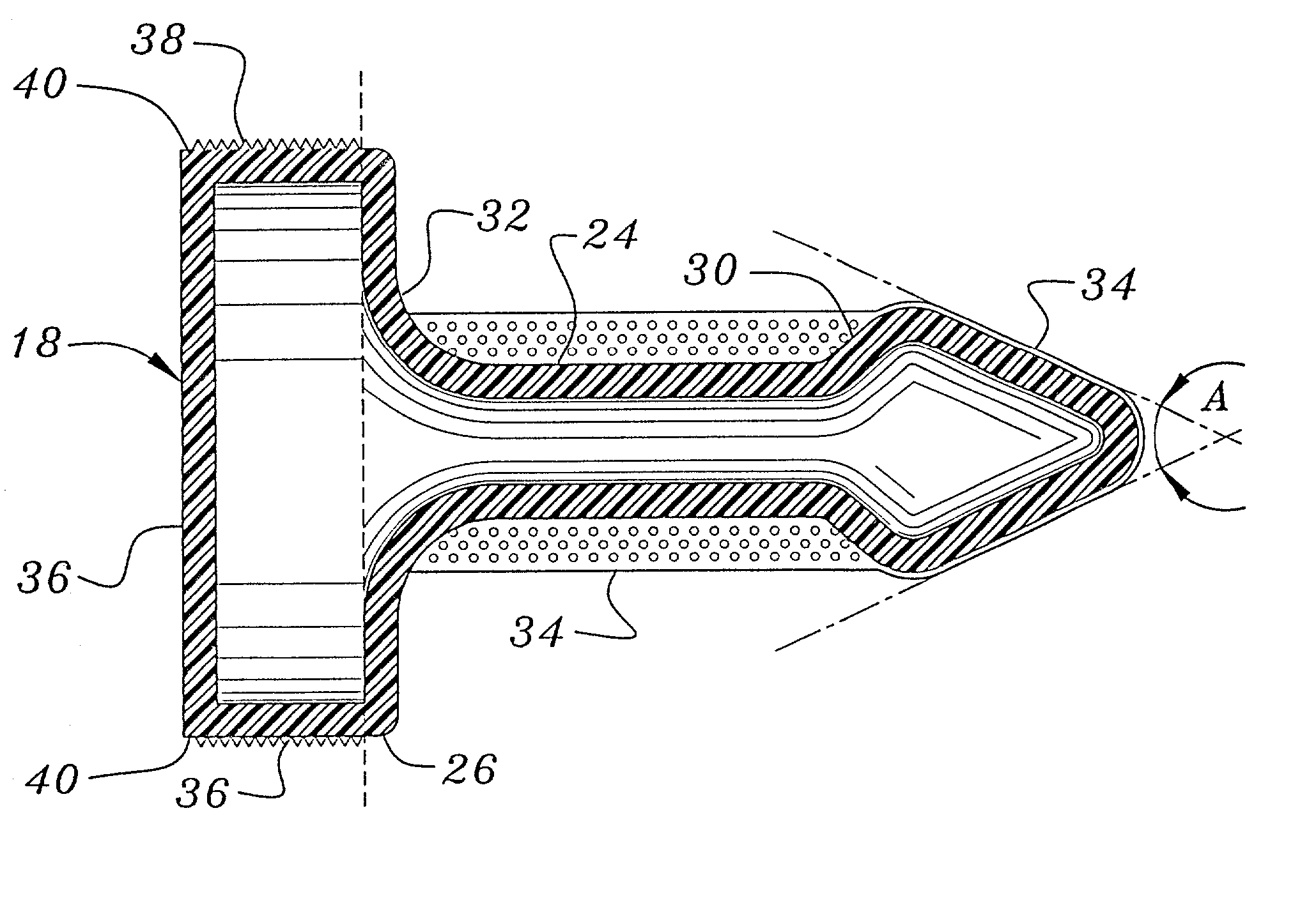
  • Exerciser for the muscles of pelvic floor
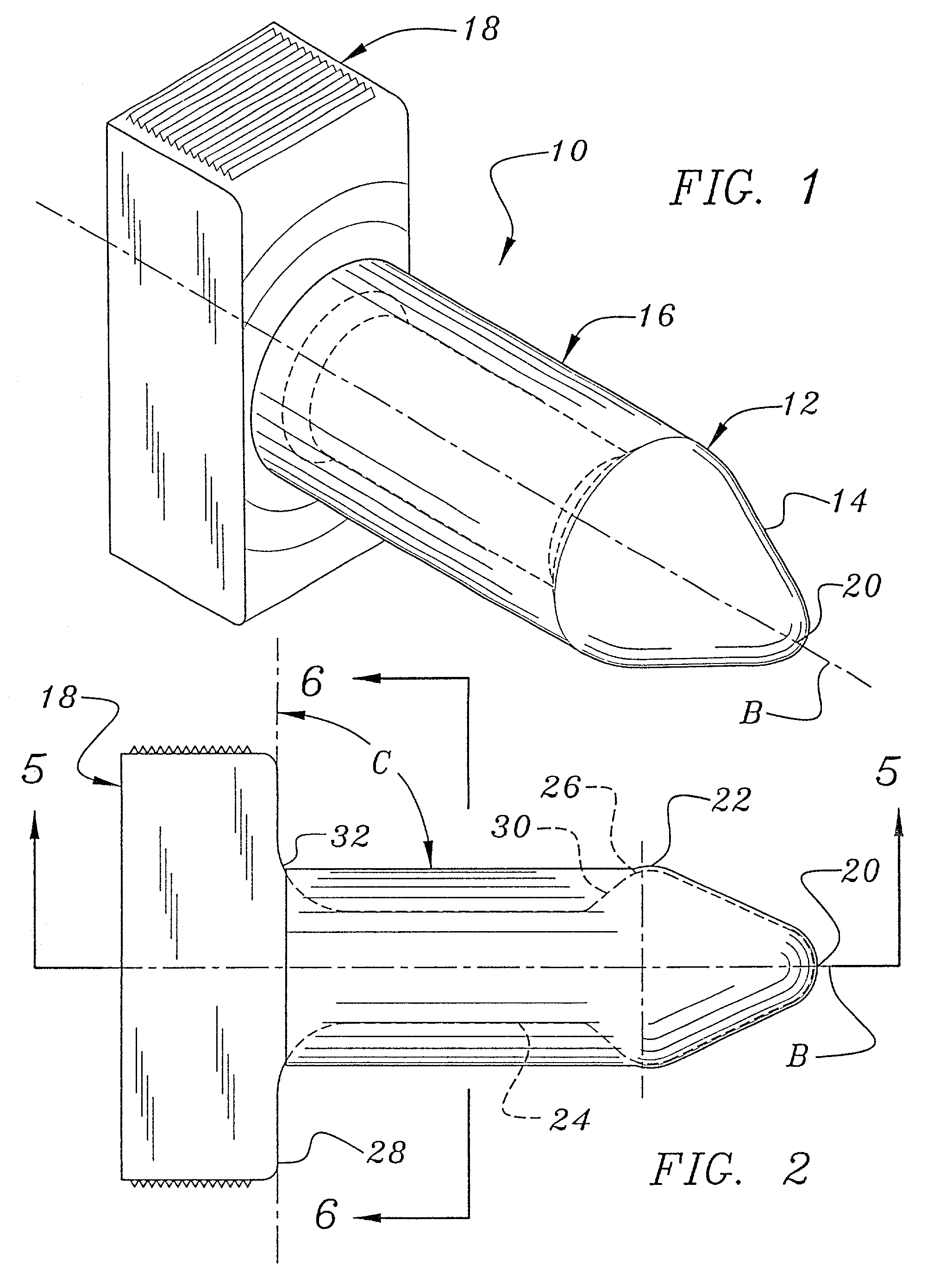
  • Exerciser for the muscles of pelvic floor
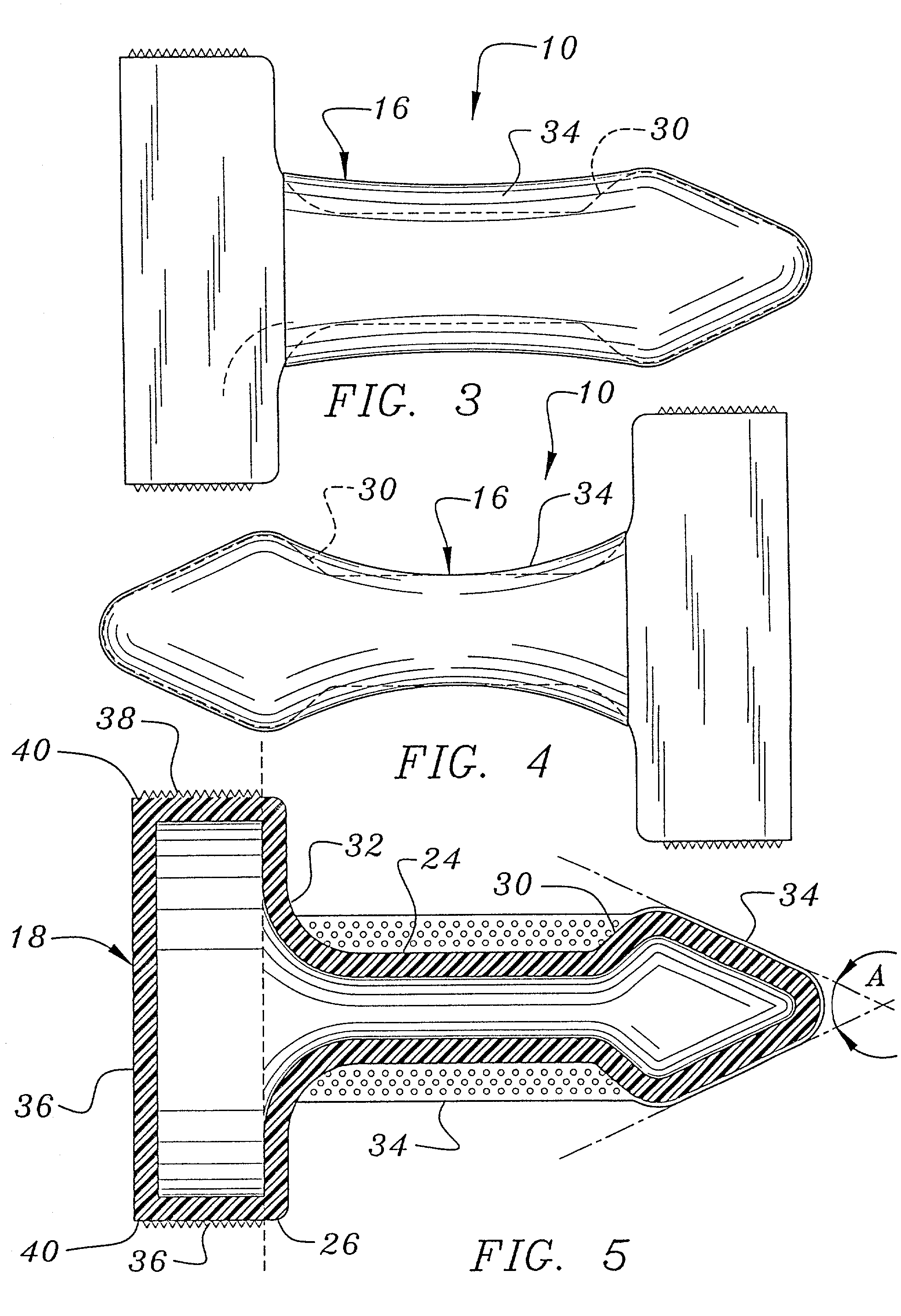
  • Exerciser for the muscles of pelvic floor

Examples


embodiment 10

[0085] The head portion 214 has a first end 220 and a second end 222, the second end of the head portion 214 being juxtaposed to the shaft portion 216. The first end 220 is formed as a blunt probe like insertion tip for ease in entering the body cavities through the vaginal or anal canals. The head portion 214 is tapered from its second end 222 to its first end 220 forming a gradual slope for comfort and ease of insertion of the device 210. The angle of the head portion 214 is generally the same as the angle A of the head portion 14 of the embodiment 10, generally 45 degrees. In this preferred embodiment, an elongated rod 262 is attached by its first end 264 to the head portion 214. The second end 266 of the rod 262 is sized and configured so that it extends through the shaft portion 216 and maybe gripped by the user. The shaft portion 216 is hollow having a bore 268 therethrough. The shaft portion 216 is made of a flexible synthetic resin, rubber, or other flexible and compressible...

sixth embodiment

[0093] As in the sixth embodiment, the shaft 716 comprises a pair of legs 786; however, in this case the legs 786 are attached to the gripper 718 connecting the legs 786 to one another. The shaft 716, conveniently legs 786, are compressible, being capable of being pressed or squeezed together. In this embodiment the legs 716 are compressed bending largely at their attachment point to the gripper 718 and also somewhat along their length. When the device 710 is inserted within a pelvic body cavity, and the muscles of the pelvic floor 42 and 44 are contracted, the legs move toward one another, and when the muscles are relaxed the legs are biased so that they move away from one another. The biasing means is established in the attachment to the gripper 718 and the properties of the material from which the device 710 is constructed. In a preferred embodiment the device 710 is constructed from a generally rigid synthetic resin, but may be constructed from any material suitable for the purp...


PUM


Abstract

An exercise device for strengthening the muscles of the pelvis, particularly the collective group of muscles involved in human sexual response, which are also important for controlling the evacuation of the intestines and the bladder. This exercise device focuses on increasing the strength, tone and endurance of these muscles. The device comprises a longitudinally extending member that includes a blunt head portion and a compressible shaft portion. The first end of the shaft portion is juxtaposed with the head portion. The first end of the shaft portion has an outwardly extending retaining slope formed thereon, particularly when the device is received within a pelvic body cavity and the muscles of the pelvic floor are at rest. The retaining slope is engageable with the retaining edge of the adjacent pelvic floor muscle platform of that pelvic body cavity to facilitate intracorporal retention within the pelvic body cavity. The compressible shaft is actively functional in creating resistance to contraction of the pelvic floor muscle platform, thereby causing the work necessary for muscle development. The second end of the shaft portion has an outwardly extending slope formed thereon. When the device is inserted into a pelvic body cavity, this outwardly extending slope is engageable with the body tissue that is adjacent to the orifice into the pelvic body cavity to prevent over insertion of the member.

Description

[0001] This application is a continuation-in-part of co-pending application Ser. No. 09 / 426,556, filed Oct. 22, 1999.[0002] 1. Field of the Invention[0003] The present invention relates to an exercise device for strengthening the muscles of the pelvic floor, particularly the collective group of muscles involved in human sexual response, which are also important for controlling the evacuation of the intestines and the bladder. The exercise device focuses on increasing the muscle endurance, strength and tone of these muscles.[0004] 2. Description of the Prior Art[0005] The lower pelvic muscles may become damaged or weakened through childbirth, lack of use, age or other reasons. One of the symptoms related to a weakening of these muscles is urinary incontinence. Various exercise devices were developed in an attempt to strengthen the pelvic floor muscles, with the specific goal of strengthening the muscles that surround the urethra to overcome urinary incontinence in women. It was disco...

Claims


Application Information

Patent Timeline
Patent Type & Authority Applications(United States)
IPC IPC(8): A63B21/02A63B23/20
CPCA63B23/20A63B21/028
Inventor STEIN, DANIEL S.
Owner UI
Why Eureka
Try Eureka