Refrigeration system for an environmental test chamber

a technology of refrigerant and environmental test chamber, which is applied in the field of environmental test chamber heating and cooling systems, can solve the problems of increasing the enthalpy of refrigeran

Inactive Publication Date: 2002-10-17
TRIESKEY GUY T
View PDF0 Cites 40 Cited by
  • Summary
  • Abstract
  • Description
  • Claims
  • Application Information

AI Technical Summary

Problems solved by technology

1. Point A to B: The refrigerant passing through the evaporator absorbs heat at an essentially constant pressure thus resulting in an increase in the enthalpy of the refrigerant. During this period the refrigerant is in the saturated region for the substantial portion of this period.
2. Point B to C: The system compressor works on the refrigerant increasing its pressure. Pressure, temperature, and thus enthalpy all increase during this period. During this period the refrigerant is in the superheated vapor region.
3. Point C to D: During this period, the refrigerant passes through the condenser that removes the heat resulting from the working process. Thus, pressure is essentially constant while the enthalpy drops significantly leaving the superheat condition and entering the saturated region again. It should be noted here that while point D is barely into the sub-cooled region on this Figure, the low stage refrigerant in conventional systems typically have point D within the saturated region, and do not even have any sub-cooling effect.
4. Point D to A: As the refrigerant passes through a metering device and into the evaporator the pressure drop causes the phase change of the refrigerant from sub-cooled to a saturated liquid, thus bringing the refrigeration cycle out of the sub-cooled region almost immediately. The PSat-TSat relationship results in a substantial temperature drop of the refrigerant. During this period the phase change also contributes to the temperature drop. It should be noted that the enthalpy is essentially constant during this period of pressure reduction. The phase change is an important part of conventional refrigeration systems.

Method used


Image

  • Refrigeration system for an environmental test chamber
  • Refrigeration system for an environmental test chamber
  • Refrigeration system for an environmental test chamber

Examples


third embodiment

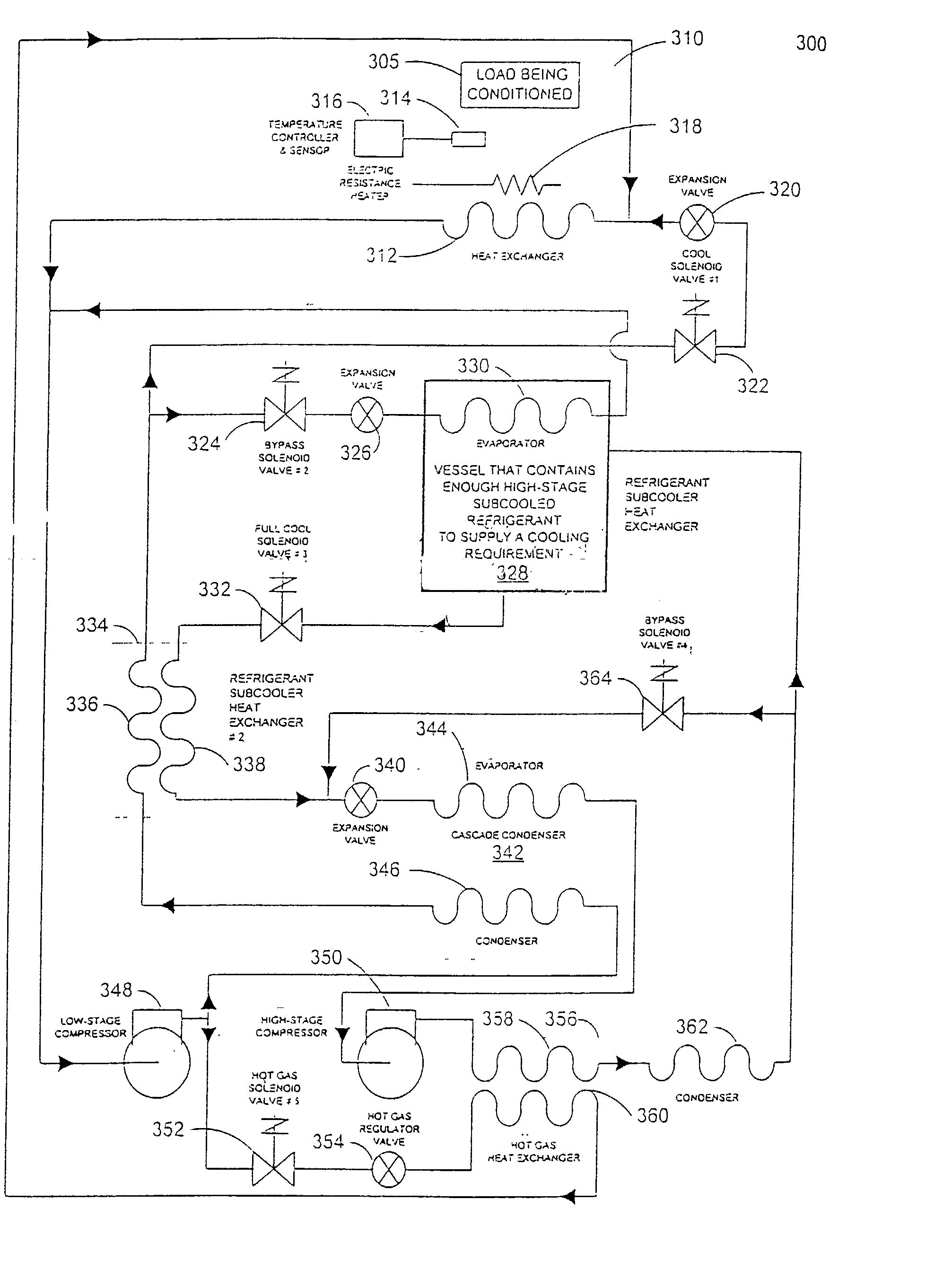
[0024] FIG. 7 is a conceptual block diagram of the present invention utilizing a cascade refrigeration and heating system and thermal storage of subcooled refrigerant.

fourth embodiment

[0025] FIG. 8 is a conceptual block diagram of the present invention utilizing a non-cascade refrigeration and heating system and thermal storage of subcooled refrigerant.

[0026] FIG. 9 shows Table 1, a valve position chart for the operation of the embodiment of the present invention shown in FIG. 5.

[0027] FIG. 10 shows Table 2, a valve position chart for the operation of the embodiment of the present invention shown in FIG. 6 and 7.

[0028] FIG. 11 shows Table 3, a valve position chart for the operation of the embodiment of the present invention shown in FIG. 8.

[0029] FIG. 12 and 13 contain Tables 4 and 5, respectively, showing the amount of compressor capacity increase obtained by subcooling the refrigerants.

[0030] It should be noted in the following discussion that many items well known to those skilled in the relevant art have been left out of the conceptual drawings and conceptual explanations regarding the prior art and the present invention. These items include, without being li...


PUM


Abstract

An environmental test chamber fast cool down and heat up system. The environmental test chamber fast cool down and heat up system comprises: an environmental test chamber having a fast cool down evaporator and fast heat up condenser coil, wherein the coil is selectively coupled either to receive a hot refrigerant gas flow or to receive a sub-cooled refrigerant flow; a cascade condenser coupled to the environmental test chamber; a primary stage sub-system coupled to the cascade condenser; a secondary stage sub-system coupled to the cascade condenser; and a thermal storage unit coupled to the primary stage sub-system and to the secondary stage sub-system. Wherein the environmental test chamber has an operational temperature down to about -125° F.

Description

[0001] This patent application is a Continuation-In-Part to U.S. patent application Ser. No. 09 / 387,315, filed Aug. 31, 1999, entitled "An Environmental Test Chamber Fast Cool Down System And Method Therefor" in the name of the same inventor and the contents of the parent are incorporated herein by reference.[0002] 1. Field of the Invention[0003] This invention relates to environmental test chamber heating and cooling systems, and more specifically, to an improved system for cooling and heating environmental test chambers using a lower capacity, smaller footprint, refrigeration and heating system in combination with thermal storage.[0004] 2. Description of the Related Art[0005] Environmental test chambers subject components within them to a variety of physically challenging test conditions. These test conditions can include acceleration tests, sand or water tests, and temperature tests. The temperature tests can consist of not only extremes of heat and cold, but also tests of large ...

Claims


Application Information

Patent Timeline
Patent Type & Authority Applications(United States)
IPC IPC(8): F25B5/02F25B7/00F25B9/00F25B40/02
CPCF25B5/02F25B7/00F25B9/002G01N17/002F25B2400/24F25D2400/30F25B40/02
Inventor TRIESKEY, GUY T.
Owner TRIESKEY GUY T
Why Eureka
Try Eureka