Hydraulic antivibration support

a technology of anti-vibration support and hydraulic technology, applied in the direction of vibration dampers, machine supports, machine frames, etc., can solve the problems of presenting a relatively high level of bellows stiffness, impede the free deformation of the compensation chamber, and hinder the operation of the anti-vibration support, etc., to achieve the effect of reducing the drawback

Inactive Publication Date: 2002-10-17
HUTCHINSON SA
View PDF0 Cites 4 Cited by
  • Summary
  • Abstract
  • Description
  • Claims
  • Application Information

AI Technical Summary

Benefits of technology

[0012] By means of these dispositions, the fold is prevented from stiffening the bellows by an arching effect while the volume of the working chamber is increasing. This significantly reduces the stiffness of the bellows, and the performance of the antivibration support is improved.

Problems solved by technology

Nevertheless, antivibration supports of that type suffer from the drawback of presenting a relatively high level of bellows stiffness, and in some cases that can impede free deformation of the compensation chamber and hinder the operation of the antivibration support.

Method used


Image

  • Hydraulic antivibration support
  • Hydraulic antivibration support
  • Hydraulic antivibration support

Examples


first embodiment

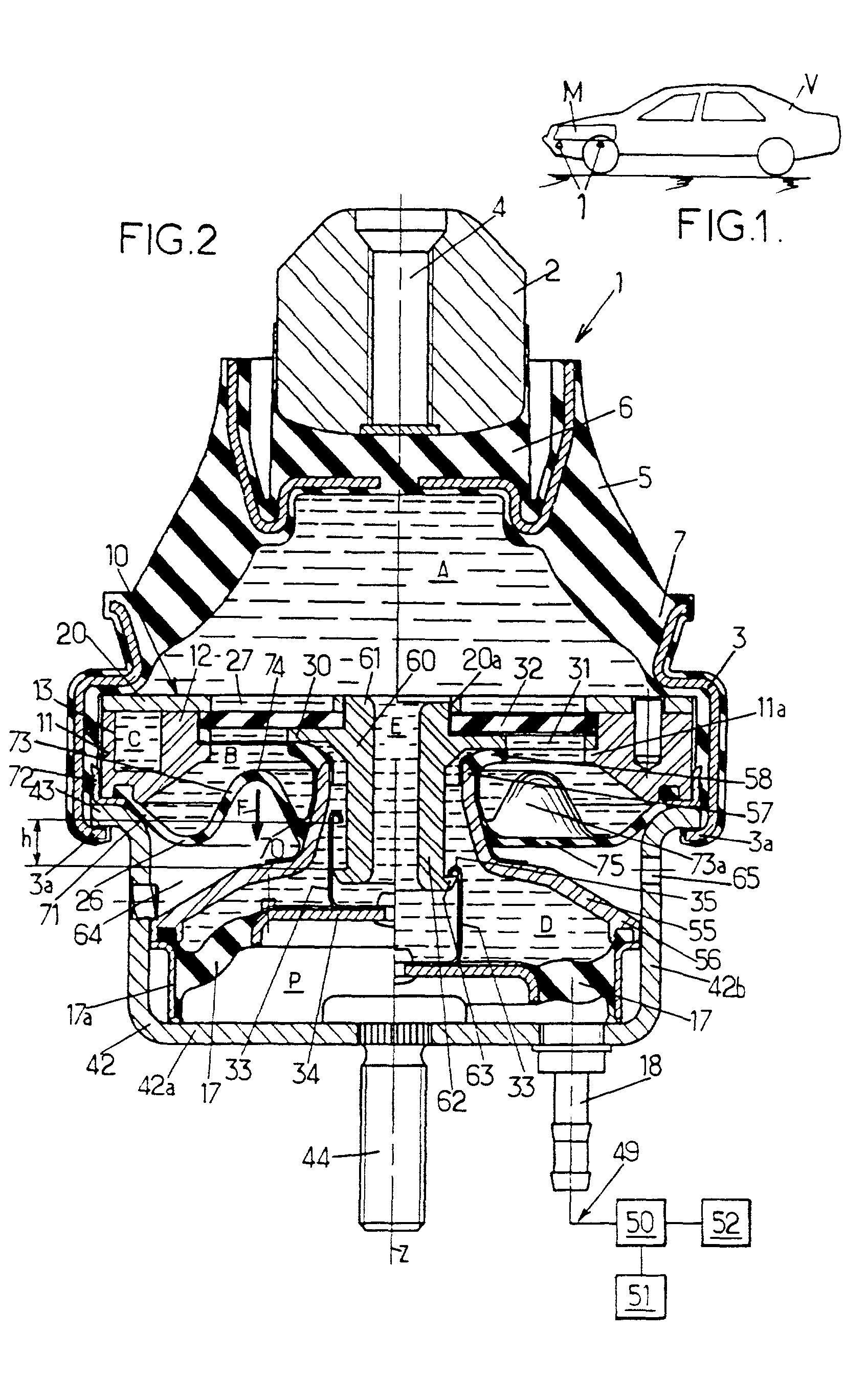
[0038] In the invention, shown in FIG. 2, the hydraulic antivibration support 1 comprises first and second strength members 2, 3 for fixing respectively to the engine unit M and to the bodywork V.

[0039] In the example described, the first strength member 2 is in the form of a stud centered on a vertical axis Z and pierced by a tapped hole 4 enabling it to be fixed to the engine unit M, while the second strength member 3 is formed by a steel ring, likewise centered on the axis Z.

[0040] These two strength members 2 and 3 are interconnected by a relatively thick elastomer body 5 which presents sufficient compression strength to be able to take up the static forces due to the weight of the engine unit. The elastomer body 5 has a bell-shaped side wall which extends between a top 6 secured to the stud 2 and an angular base 7 which is secured to the ring 3.

[0041] The second strength member 3 surrounds a rigid partition 10 which co-operates with the elastomer body 5 to define a working cham...

second embodiment

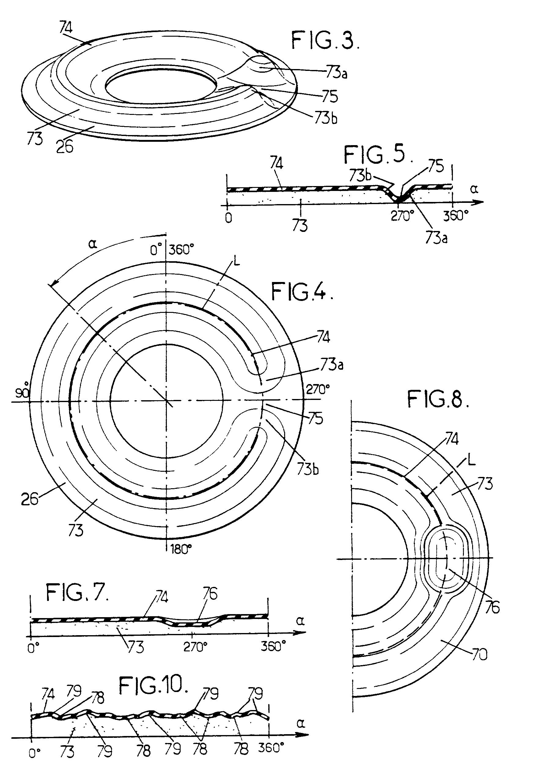
[0080] In the invention, as shown in FIGS. 6 to 8, the ridge 74 of the annular fold 73 in the bellows is provided as before with a depression 76 whose concave side faces towards the compensation chamber B, but in this case the depression extends solely over a fraction of the height of the fold.

[0081] In this second embodiment, as in the first embodiment as described above, the depression formed in the fold 73 of the bellows is obtained when molding the bellows 26.

[0082] In a third embodiment, shown in FIG. 9, the depression 76, e.g. identical or similar in shape to the depression 76 of the second embodiment as described above, can be obtained by means of a rigid finger 77 or some other presser element, e.g. belonging to the body 11 of the partition 10 and projecting axially downwards in the compensation chamber B so as to press locally on the ridge 74 of the fold 73.

[0083] Under such circumstances, the bellows 26 can be molded with an annular fold 73 that is circularly symmetrical a...

fourth embodiment

[0084] Finally, as shown in FIG. 10, in the invention, the bellows 26 can be irregular in shape at the ridge 74 of its fold 73, forming a succession of depressions 78 each having a concave side open towards the compensation chamber B, and portions 79 projecting towards the compensation chamber B. This irregular shape can be obtained in particular during molding of the bellows 26.


PUM


Abstract

The hydraulic antivibration support comprises two strength members interconnected by an elastomer body defining part of a liquid-filled working chamber which communicates via a constricted passage with a compensation chamber that is separated from said working chamber by a rigid partition. The compensation chamber is defined by an annular bellows presenting an annular fold which projects into the compensation chamber and which is of a shape that does not present circular symmetry.

Description

[0001] The present invention relates to hydraulic antivibration supports, intended in particular for mounting the engine of a motor vehicle on the structure of the vehicle.[0002] More particularly, the invention relates to a hydraulic antivibration support for interconnecting first and second rigid elements to damp vibration between said elements, the support comprising:[0003] first and second rigid strength members for fixing respectively to the first and second rigid elements;[0004] an elastomer body interconnecting the first and second strength members;[0005] a hydraulic working chamber filled with liquid, and defined at least in part by the elastomer body; and[0006] a flexible bellows of elastomer material defining at least part of a hydraulic compensation chamber filled with liquid which communicates with said working chamber via a constricted passage, said bellows presenting a central portion secured to a member carried by the second strength member and a periphery secured to ...

Claims


Application Information

Patent Timeline
Patent Type & Authority Applications(United States)
IPC IPC(8): F16F13/10F16F13/26
CPCF16F13/268F16F13/103
Inventor GENESSEAUX, ANDRE
Owner HUTCHINSON SA
Why Eureka
Try Eureka