Structure including a plurality of cells of cured resinous material, method of forming the structure and apparatus for forming the structure

a technology of cured resin and structure, applied in the field of structure including a plurality of cells of cured resinous material, method of forming structure and apparatus for forming structure, can solve the problems of leakage or diffuse through the structure, contaminant of sensors and solar cell arrays, and loss of inflatant mass with increasing antenna siz

Inactive Publication Date: 2002-10-31
THE JOHN HOPKINS UNIV SCHOOL OF MEDICINE
View PDF1 Cites 16 Cited by
  • Summary
  • Abstract
  • Description
  • Claims
  • Application Information

AI Technical Summary

Problems solved by technology

As a result, lost inflatant mass would decrease with increasing antenna size.
Any gas that does leak or diffuse through the structure over time will be a possible contaminant to sensors and solar cell arrays.
A mechanical approach has been successful in a number of cases, but it is limited to smaller structures due to the inefficiencies inherent in joints, fasteners and sliding surfaces.
A number of deployment failures have occurred that were traced to environmental effects, such as thermal expansion and contraction or to tribological effects.
However, the energy requirements for heating can be very taxing on a spacecraft's power system.
The residual stresses developed in a composite structure as it is heated during curing and cooled to ambient, and possibly very low, temperatures add complication to the design.
Another detrimental factor of such techniques is outgassing of the resin as it is processed.
Again, this presents a contamination issue.
The primary drawback to this technology has been the inability to develop a process that allows the resin to be cured with UV while the composite material is being compacted.
A composite structure cured with no compacting load will have a substantially reduced performance due to low fiber volume fraction.
Unfortunately, all of the commercial foaming technology produces a gas that can become a contaminant as it diffuses through the polymer.
A two component foaming technology is very difficult to control in terms of cell size and cell size distribution throughout a structure's cross-section.
These structures have limited application, as the spacecraft must be spinning.
The tubular boom is, however, limited by its buckling strength at the root.
This technology is limited by the amount of strain that can be placed on the longerons in the storage container.

Method used


Image

  • Structure including a plurality of cells of cured resinous material, method of forming the structure and apparatus for forming the structure
  • Structure including a plurality of cells of cured resinous material, method of forming the structure and apparatus for forming the structure
  • Structure including a plurality of cells of cured resinous material, method of forming the structure and apparatus for forming the structure

Examples


Embodiment Construction

)

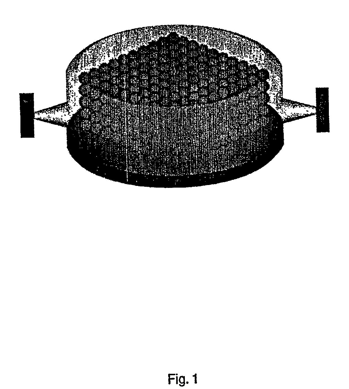
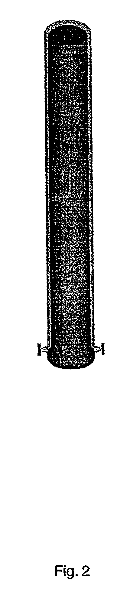
[0037] The present invention can satisfy the need or desire to form structures in place. Additionally, the present invention can fulfill the need to create lightweight high strength structures. In particular, the present invention can be utilized to form elongated lightweight high strength structures. While the present invention may be particularly useful in space, it may be utilized for terrestrial as well as undersea applications.

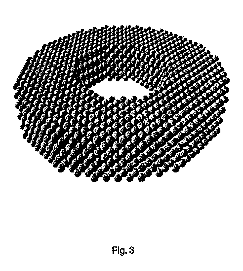
[0038] Structures according to the present invention include a plurality of cells of cured resinous material. The cells may be arranged in a plurality of planes. Each plane may include the same or a different number of cells. The cells may all be aligned with each other in a direction perpendicular to the planes. Alternatively, the cells may be arranged aligned in another direction. For example, the cells in one plane could be arranged with their centers spaced one-half cell diameter away from the cells in an adjacent plane. The cells could be aligned in...


PUM

PropertyMeasurementUnit
thickaaaaaaaaaa
thickaaaaaaaaaa
area massaaaaaaaaaa

Abstract

A structure that includes a plurality of cells of a cured resinous material. Each cell is joined to at least one other cell.

Description

[0001] 1. Field of the Invention[0002] The present invention relates to a structure that may be formed of a plurality of resinous cells, a method and an apparatus for forming such a structure. The structure may be formed in place where it is to be utilized.[0003] 2. Description of Related Art[0004] In many situations, it may be desirable to form a structure in place where it is to be utilized. Sometimes, a structure is preformed and then assembled in place. One proposed application of such structures is in outer space. For example, it has been proposed to form spacecraft or portions of spacecraft from prefabricated inflatable structures. Prefabricated inflatable structures have also been proposed for forming structures on other celestial bodies, such as moon bases and underground caverns. Such structures have also been proposed for use in terrestrial applications.[0005] Space-based structures that are assembled and / or formed in place can include a plurality of layers of material wit...

Claims


Application Information

Patent Timeline
Patent Type & Authority Applications(United States)
IPC IPC(8): B29C44/34B64G1/22B64G99/00C08J9/00C08J9/16C08J9/32
CPCB29C44/34B64G1/222B64G9/00C08J9/32C08J9/00C08J9/16B64G2001/224B64G99/00B64G1/2227
Inventor BIERMANN, PAUL J.ROBERTS, JACK C.
Owner THE JOHN HOPKINS UNIV SCHOOL OF MEDICINE
Why Eureka
Try Eureka