
Medication record system and dispenser

a technology of medication record system and dispenser, which is applied in the direction of confirming the correctness of markings, rigid containers, packaging goods types, etc., can solve the problems of high cost of electronic devices, complicated design, and inability to note whether medication has been taken

Inactive Publication Date: 2002-11-21
KOZLOWSKI NANCY MS
View PDF45 Cites 45 Cited by
  • Summary
  • Abstract
  • Description
  • Claims
  • Application Information

AI Technical Summary

Benefits of technology

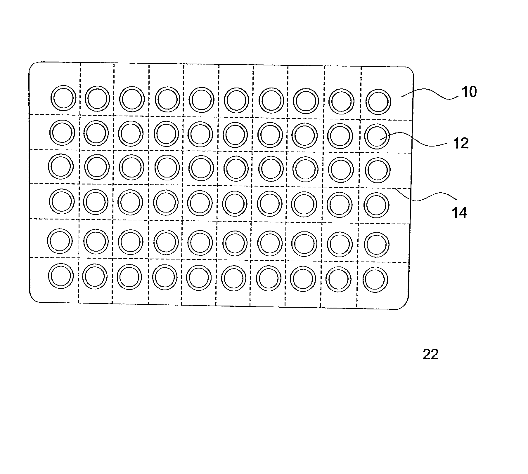
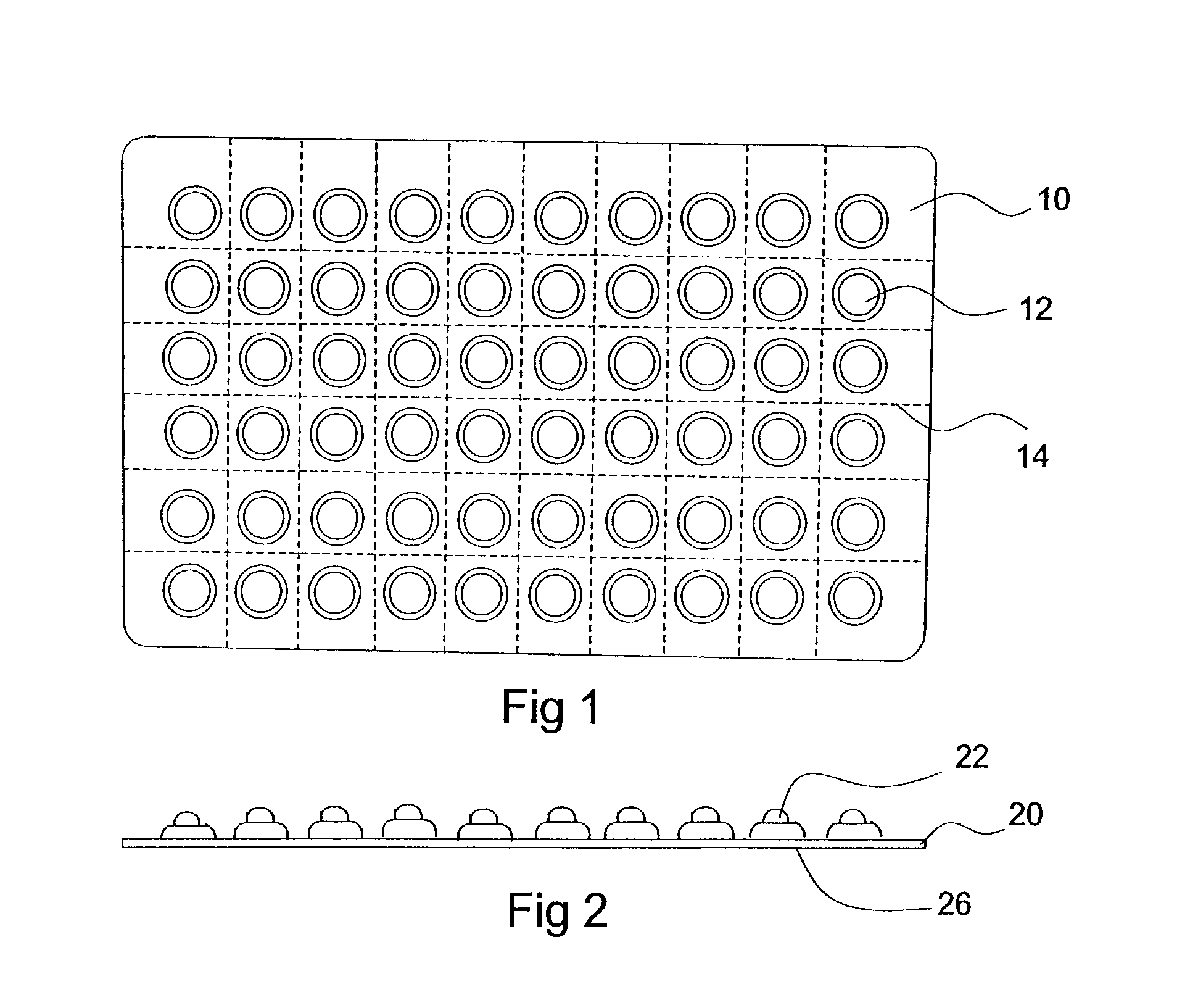
0013] FIG. 1 is a plan view of the device containing multiple raised tabs configured into a pill card design.

Problems solved by technology

One failing of the electronic systems is the high cost of the electronics.
Another failing is their inability to note whether medication has been taken.
Furthermore, they can be complicated in design and therefore difficult to operate.
Errors and misuse can undermine the effectiveness of medication and can be dangerous to the person using the medication.
The problem is exacerbated when a person is using multiple medications during the same time period.

Method used


Image

  • Medication record system and dispenser
  • Medication record system and dispenser
  • Medication record system and dispenser

Examples


second embodiment

[0094] FIG. 29a shows an injection-molded design for the dimpled blister. In this embodiment, two larger rings of plastic 292, 294 form an internal cut-out that is thinner than the remaining plastic in the blister and provide the mechanism for collapse. Once the blister is depressed, the rings of plastic 292, 294 collapse in the manner shown in FIG. 29b, providing a more uniform collapse. This design again reduces the likelihood of an uneven shape forming after the blister is depressed that could be misread tactilely by the user. FIG. 29c shows a top view of the collapsed blister described in FIG. 29b.

third embodiment

[0095] FIG. 30a shows an injection-molded design for the dimpled blister 300. In this embodiment, two larger rings of plastic 302, 304 form an external cut-out that is thinner than the remaining plastic in the blister and provide the mechanism for collapse. Once the blister is depressed, the rings of plastic 302, 304 collapse in a controlled manner as shown in FIG. 30b. This design again reduces the likelihood of an uneven shape forming after the blister is depressed that could be misread tactilely by the user. FIG. 30c shows a top view of the collapsed blister described in FIG. 30b.

[0096] FIG. 31 shows a non-uniformly collapsed blister 310 of the style shown in FIG. 30. When a package contained the blister cards is inadvertently damaged or pressure is accidentally applied to the blister on a side, the blister will collapse in the fashions shown, providing a different visual and tactile cue for the user. The user will then be able to distinguish a properly collapsed blister from one...

fourth embodiment

[0097] FIG. 32 shows an injection-molded design for the dimpled blister 320. In this embodiment, two larger rings of plastic 322, 324 form an internal cut-out that is thinner than the remaining plastic in the blister and that is separated from the top of the blister. These rings provide the mechanism for collapse. Once the blister is depressed, the rings of plastic 322, 324 collapse in a controlled manner as shown in FIG. 33. As in the previous embodiments, this design reduces the likelihood of an uneven shape forming after the blister is depressed that could be misread tactilely by the user.

[0098] FIG. 34 shows the blister of FIG. 32 as used in combination to hold medication and as a medication tracker. The blister card 340 contains the medication 342 between the blister 344 and the backing card 346 or materials well known in the art. When the blister 344 is depressed, the medication 342 pushes through the backing card 346, tearing open the backing card 346 and releasing the medica...


PUM


Abstract

The present invention relates to a medication management system that is simple, reliable and extremely easy to use. It comprises a label having a plurality of raised tabs that are depressed upon taking a medication to provide a tactile and a visual record of medication use. It can be secured to the medication container, and thus is not subject to being misplaced or forgotten. The system can be integrated with a pharmacy's computerized pharmaceutical record and prescription label printing system or it can be a stand-alone paste-on label. Alternatively, it can be used in combination with blister packs to dispense medication while maintaining a record of use. The label can be in the form of an overlay, which is placed over a preprinted container or a container having a prescription label. The use of a pressure sensitive releasable adhesive permits the removal of the overlay label in the event that is it necessary to read information on the underlying label. The underlying label is provided with a plurality of raised tabs that correspond to the number of doses to be taken per day and the number of days for which the medication is to be taken.

Description

[0001] The present application claims priority to U.S. provisional application No. 0 / 292,158 filed May 8, 2001 nd to U.S. patent application Ser. No. 09 / 583,125 filed May 30, 2000, which claims priority to U.S. provisional patent application serial No. 60 / 136,796 filed May 29, 1999. This application incorporates by reference, as though recited in full, the disclosure of provisional application 60 / 292,158, co-pending patent application 09 / 583,125, and provisional application 60 / 136,796.[0002] 1. Field Of the Invention[0003] This invention relates to an improved system for facilitating the dose record keeping and dispensing of medication, and more particularly to a system for aiding people in the correct administration of medication that is taken over an extended period of time.[0004] 2. Brief Description of the Prior Art[0005] It is well recognized that it is essential to assist people in establishing a medication regime, and to enable people to easily keep track of when and if medic...

Claims


Application Information

Patent Timeline
Patent Type & Authority Applications(United States)
IPC IPC(8): A61J1/03A61J7/04
CPCA61J1/035A61J7/04G09F2003/0273G09F2003/0216G09F3/0291
Inventor KOZLOWSKI, NANCYWEBB, NICHOLAS
Owner KOZLOWSKI NANCY MS
Learn More