Method and apparatus to quickly increase the concentration of gas in a process chamber to a very high level

a technology of process chamber and gas concentration, which is applied in the direction of ozone preparation, electrical apparatus, basic electric elements, etc., can solve the problems of inability to generate an ozone/oxygen gas mixture with a higher concentration of ozone gas, increase the output of ozone, and underutilize the ozone capacity, etc., to achieve high efficiency, high ozone demand, and efficient use of ozon

Inactive Publication Date: 2002-11-21
FSI INTERNATIONAL INC
View PDF0 Cites 17 Cited by
  • Summary
  • Abstract
  • Description
  • Claims
  • Application Information

AI Technical Summary

Benefits of technology

0014] The invention is directed in one aspect to methods of efficiently using ozone in the treatment of in-process microelectronics devices and systems for accomplishing the same. Using a high efficiency method disclosed herein, processes employing ozone may be carried out using smaller ozone generators than would otherwise be possible while meeting the ozone requirement of the process. Alternatively, for a given size generator, a higher ozone demand may be serviced.

Problems solved by technology

During the remainder of the process, however, ozone capacity is underutilized.
Currently, it is not practical to generate an ozone / oxygen gas mixture with a higher concentration of ozone gas.
Thus, where large amounts of ozone are required, the flow rate of oxygen into the generator may be increased resulting in the output of increased amounts of ozone.
Unfortunately, in processes employing ozone in which the demand for ozone is intermittent or otherwise variable over time, the ozone capacity is not used efficiently.
Ozone generators cannot simply be turned on and off during most processes without deleterious effects because of the time required for ozone generators to reach steady state.
The additional time that would be required may slow process time and hence reduce throughput dramatically.
Consequentially, during periods of off-demand, ozone is wasted.

Method used


Image

  • Method and apparatus to quickly increase the concentration of gas in a process chamber to a very high level
  • Method and apparatus to quickly increase the concentration of gas in a process chamber to a very high level
  • Method and apparatus to quickly increase the concentration of gas in a process chamber to a very high level

Examples


Embodiment Construction

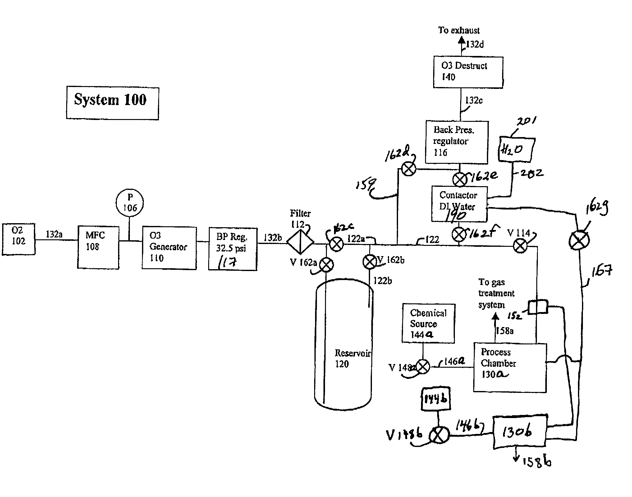
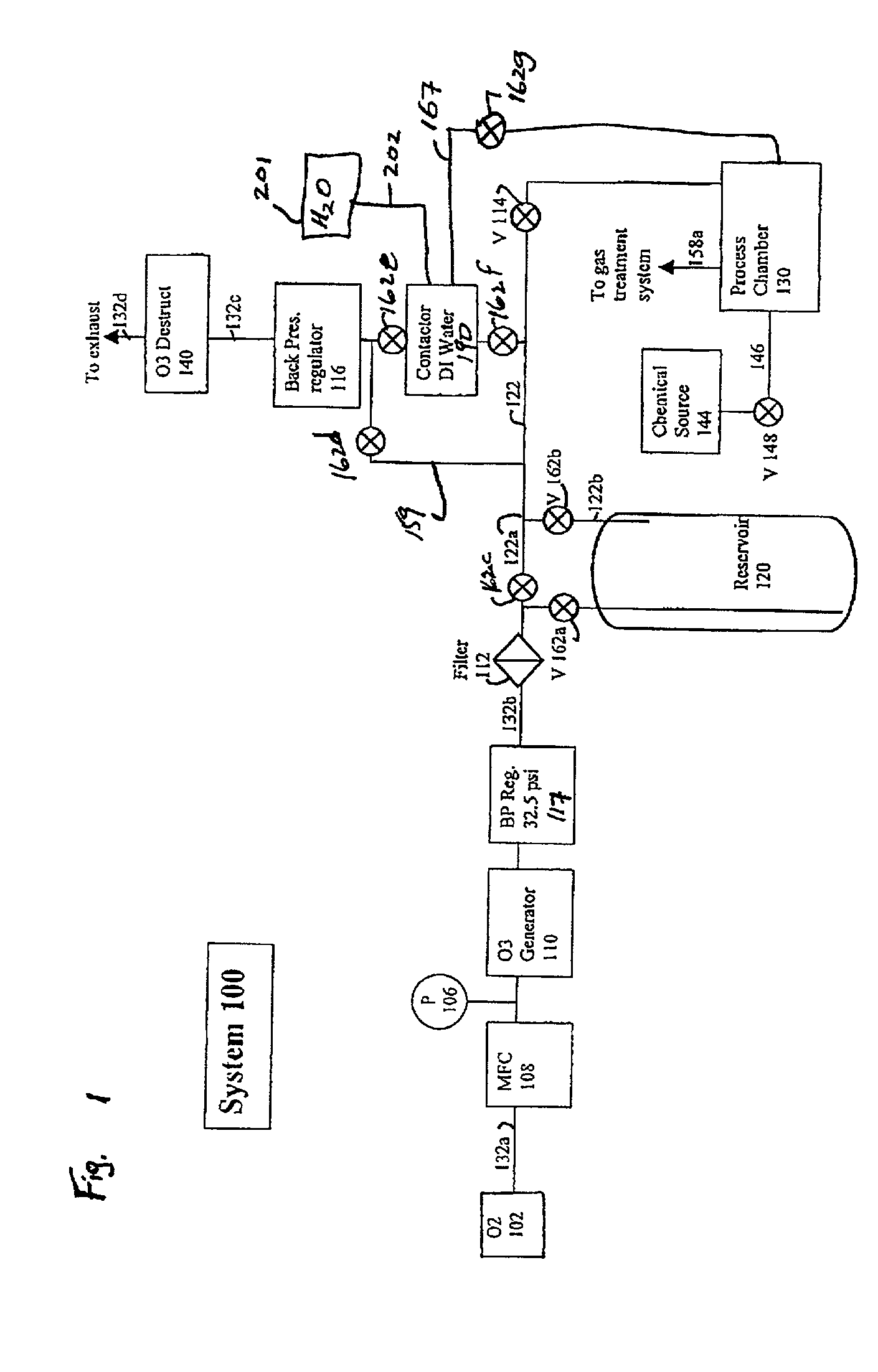
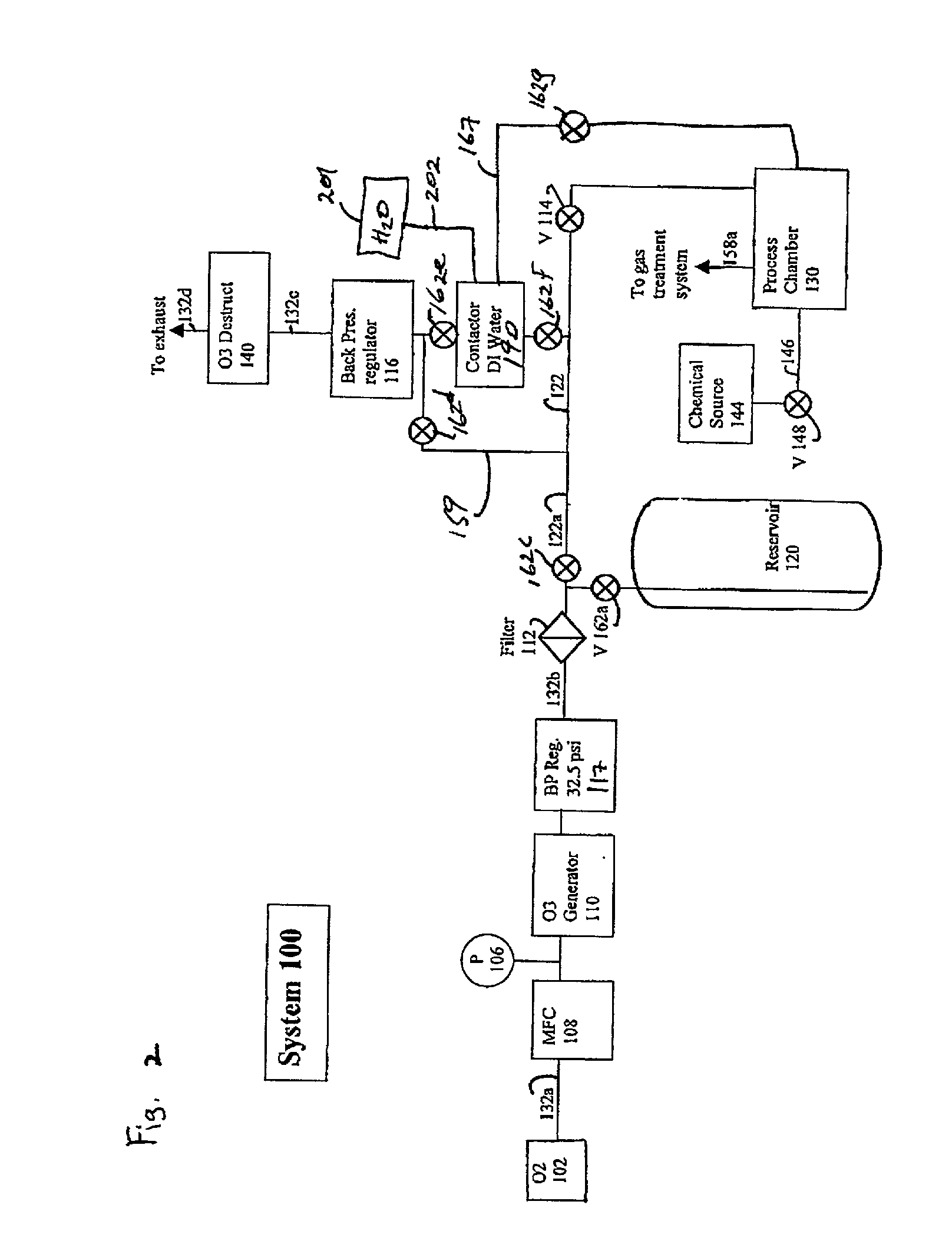
[0076] Oxygen flowed into a Semozon Model 90.2 ozone generator manufactured by ASTeX (Woburn, Mass.). The ozone generator was operated at maximum voltage corresponding to a voltage of 5000-6000 V and produced an ozone / oxygen gas mixture at a flow rate of 10 slpm. The resultant gas mixture was 10% ozone. The gaseous mixture of ozone in oxygen was output from the generator at a pressure of approximately 43 psig (296,475 Pa gauge). In the comparative examples, the ozone / oxygen gas mixture generated by the ozone generator was delivered directly into a Mercury MP.RTM. Spray Processor loaded with bare silicon wafers at 10 slpm. In the inventive example, the output of the generator was delivered to an ozone storage reservoir comprising two 8 liter cylinders in parallel. The cylinders were of stainless steel construction with PTFE lining. The ozone storage reservoir was filled to approximately 43 psig (296,475 Pa gauge) over a period of 10-15 minutes. After filling the reservoir, the ozone ...


PUM

PropertyMeasurementUnit
pressureaaaaaaaaaa
pressureaaaaaaaaaa
volumeaaaaaaaaaa

Abstract

An in-process microelectronic device may be treated by providing a process chamber with an in-process microelectronic device therein, providing an ozone generator and an ozone storage reservoir, the ozone storage reservoir in fluid communication with the ozone generator and the process chamber, generating ozone with the ozone generator for a first period of time and delivering the ozone to the ozone storage reservoir; and subsequently providing ozone from the ozone storage reservoir and the generator to the process chamber during a second period of time different from the first period of time and exposing the in-process microelectronic device thereto.

Description

BACKGROUND OF INVENTION[0001] In the area of semiconductor processing, ozone is used as a process chemical in the manufacture of microelectronic devices. For example, ozone may be used in a variety of dry techniques and wet techniques to remove unwanted organic material from semiconductor substrates. It is also used to form layers or features on in-process devices.[0002] Dry techniques typically involve the use of ozone gas and optionally ultraviolet light to remove unwanted materials from a semiconductor substrate. The use of ozone gas in a dry process has been disclosed in U.S. Pat. No. 5,709,754.[0003] Wet techniques involve the use of ozone and a liquid such as water. The use of aqueous ozone in a wet process has been disclosed in U.S. Pat. No. 6,080,531. In accordance with U.S. Pat. No. 6,080,531, a treating solution of ozone and optionally bicarbonate or other suitable radical scavenger is used to treat a substrate for use in an electronic device. The method is particularly we...

Claims


Application Information

Patent Timeline
Patent Type & Authority Applications(United States)
IPC IPC(8): C01B13/10H01L21/311H01L21/316
CPCC01B13/10H01L21/31662H01L21/31612H01L21/31138
Inventor CHRISTENSON, KURTNELSON, STEVEN L.
Owner FSI INTERNATIONAL INC
Why Eureka
Try Eureka