
Method and apparatus for lifting, leveling, amd underpinning a building foundation

a technology for building foundations and methods, applied in foundation engineering, bulkheads/piles, construction, etc., can solve problems such as excessive stress on the foundation, improper penetration angle, and insufficient depth of screw anchors, and achieve the effect of leveling the foundation

Inactive Publication Date: 2002-11-28
PROVOST MARK A
View PDF0 Cites 30 Cited by
  • Summary
  • Abstract
  • Description
  • Claims
  • Application Information

AI Technical Summary

Benefits of technology

0006] The present invention teaches a method and apparatus for leveling a building foundation. The method including excavating a cavity below the portion of the foundation to be raised at regular intervals and using and an over-sized screw anchor driven under the foundation at approximately 15 degrees relative to the foundation edge at each of the excavated cavities, the anchor having relatively large helical screw flighting or auger plate to insure support at relatively shallow depths, providing a bed of dry cement mix at each of the excavated cavities, installing an anchor jack-plate having a

Problems solved by technology

Several problems occur when these procedures are implemented.
In some case the screw anchor is not driven to a sufficient depth to insure stability or the angle of penetration is improper.
Therefore, when the jack is loaded, the anchor bends or excessive stress is placed on the foundation due to improper point loading.
Where cement piers are used they are often not level, thereby causing the jacks to stress the foundation by improper point loading.

Method used


Image

  • Method and apparatus for lifting, leveling, amd underpinning a building foundation
  • Method and apparatus for lifting, leveling, amd underpinning a building foundation
  • Method and apparatus for lifting, leveling, amd underpinning a building foundation

Examples


Embodiment Construction

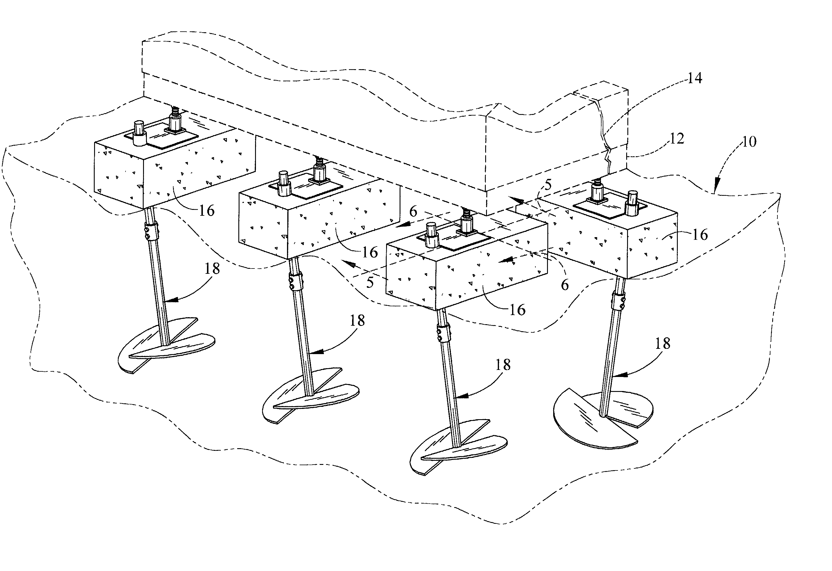
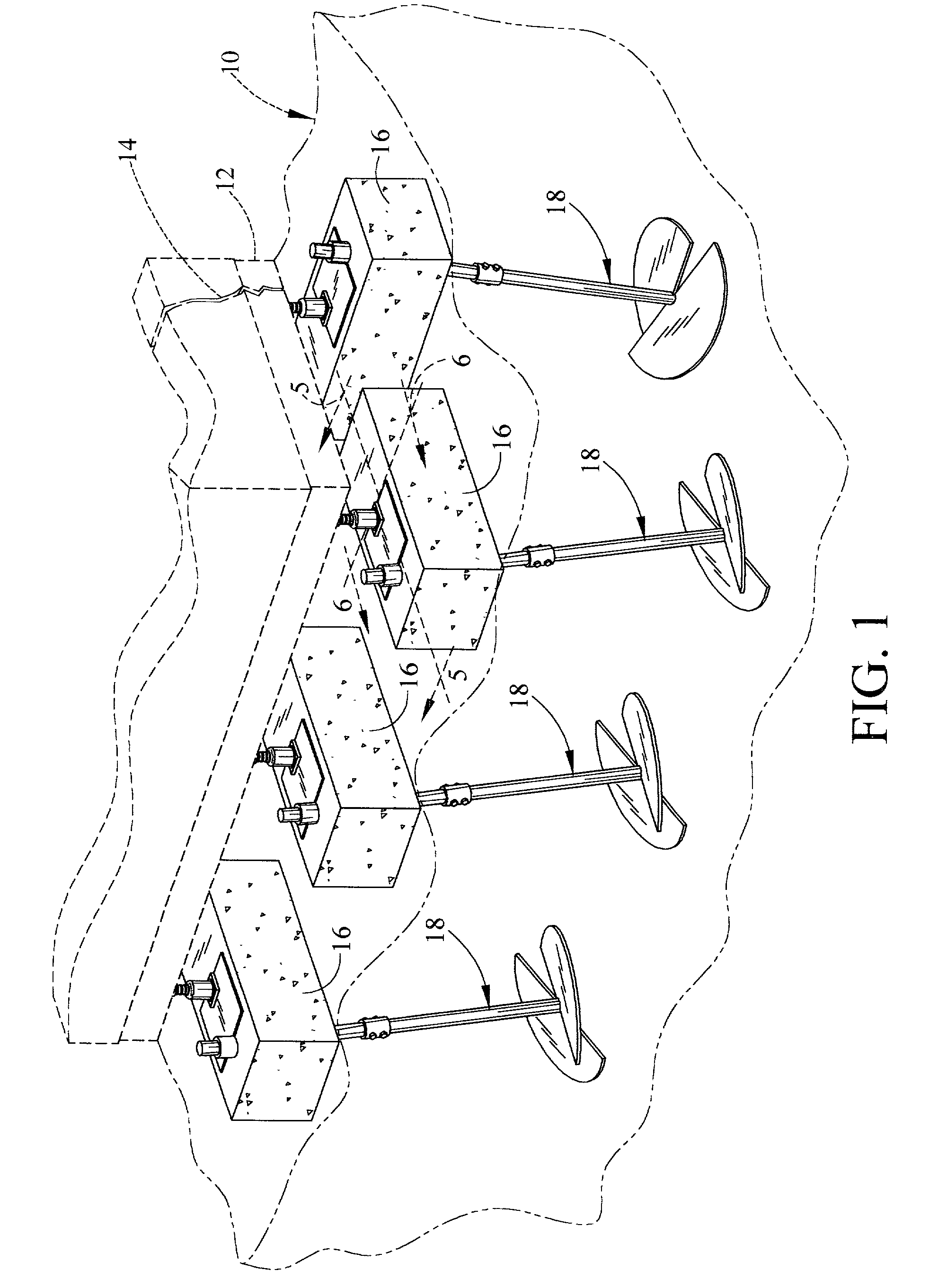
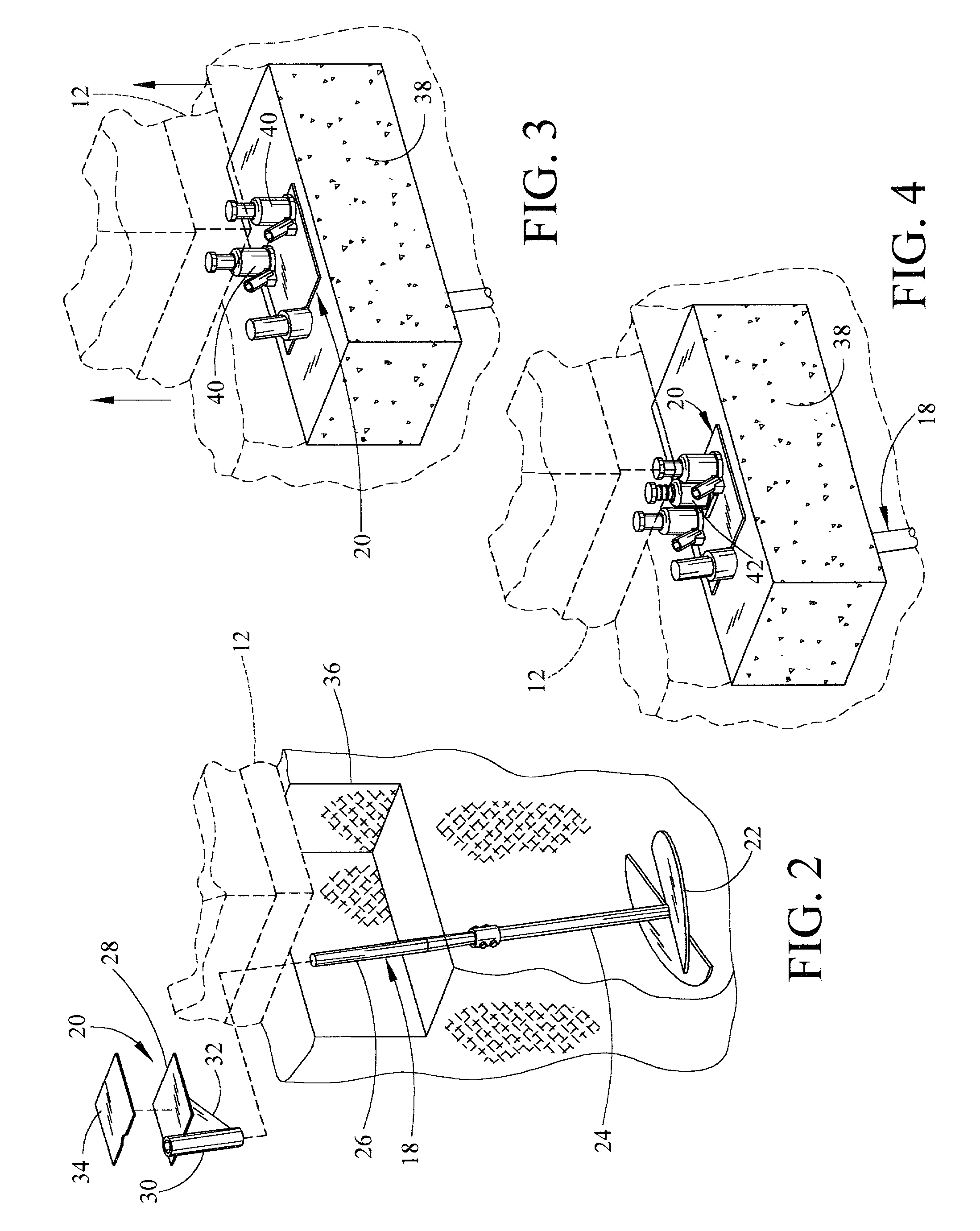
[0014] As illustrated in FIG. 1, foundation leveling is usually required as a result of movement in the soil 10 providing support for the foundation. Such movement often results in cracks 14 in the floor slabs 12, etc. In such cases it has been found that floating piers 16 stabilized by a screw anchor 18 located at strategic points around the foundation 12 are very effective and inexpensive in raising and leveling a foundation if applied in a unique manner using a unique jack plate assembly 20 as seen in FIG. 2. The leveling apparatus includes the screw anchor assembly 18, which is comprised of the screw blade portion 22 and the shaft portion 24 which may be extended by coupling additional shaft lengths as necessary to allow the anchor to reach a stable earth formation. Making the screw auger blades or flighting 22 oversized, relative to general practice, typically in the range of 18 to 24 inches in diameter, stability may be achieved at a much shallower depth. The apparatus further...


PUM


Abstract

A method and apparatus for leveling a building foundation including excavating a cavity below the portion of the foundation to be raised at regular intervals and using and an oversized screw anchor driven under the foundation at approximately 15 degrees relative to the foundation edge at each of the excavated cavities, the anchor having relatively large helical screw flighting or auger plate to insure support at relatively shallow depths. Each excavated cavity is provided with a bed of dry cement mix. The method includes the steps of installing an anchor jack-plate upon said bed of dry cement the jack plate having a collar and gusset attached thereto slidable upon the screw anchor shaft, providing a pair of hydraulic jacks atop the anchor plate, taking a portion of the foundation load on each jack, thereby directing the load at each jack in axial alignment with the helical screw anchor flighting or auger plate, setting the cement by wetting and welding the collar of the anchor jack-plate to the screw anchor shaft only when the foundation is considered level, installing a screw jack at each lifting point and removing the hydraulic jacks and pumping cement into any voids detected below the foundation footing.

Description

[0001] 1. Field of the Invention[0002] This invention relates generally to a method and apparatus for lifting, leveling, and underpinning a building foundation where such foundation has fallen out of plumb as a result of soil movement below the foundation and more particularly to foundation leveling apparatus that utilizes screw anchors as an integral part of a support column.[0003] 2. General Background[0004] The prior art teaches various methods for raising, leveling, and underpinning foundations that have dropped or cracked as a result of movement of the supporting soil on which the foundation was laid. These concepts include the process of excavating a portion of the soil from below the foundation and constructing some form of underpinning in the form of columns which serve as a new footing for the foundation at strategic points and using these columns as a base for supporting screw jacks to bring the building foundation back into a level plane. Others teach the use of screw anc...

Claims


Application Information

Patent Timeline
IPC IPC(8): E02D35/00
CPCE02D35/00
Inventor PROVOST, MARK A.
Owner PROVOST MARK A
Features
  • Generate Ideas
  • Intellectual Property
  • Life Sciences
  • Materials
  • Tech Scout
  • Unparalleled Data Quality
  • Higher Quality Content
  • 60% Fewer Hallucinations
Learn More