Connector for electronic appliance
a technology for connecting devices and electronic equipment, applied in the direction of connection, electrical apparatus, coupling device connection, etc., can solve the problems of reducing the connection stability between the socket and the plug of the connector may not be easily connected or separated from each other, and the connection stability between the plug and the cable of the electronic equipment may be reduced. , to achieve the effect of easy separation of the plug from the sock
- Summary
- Abstract
- Description
- Claims
- Application Information
AI Technical Summary
Benefits of technology
Problems solved by technology
Method used
Image

Examples
first embodiment
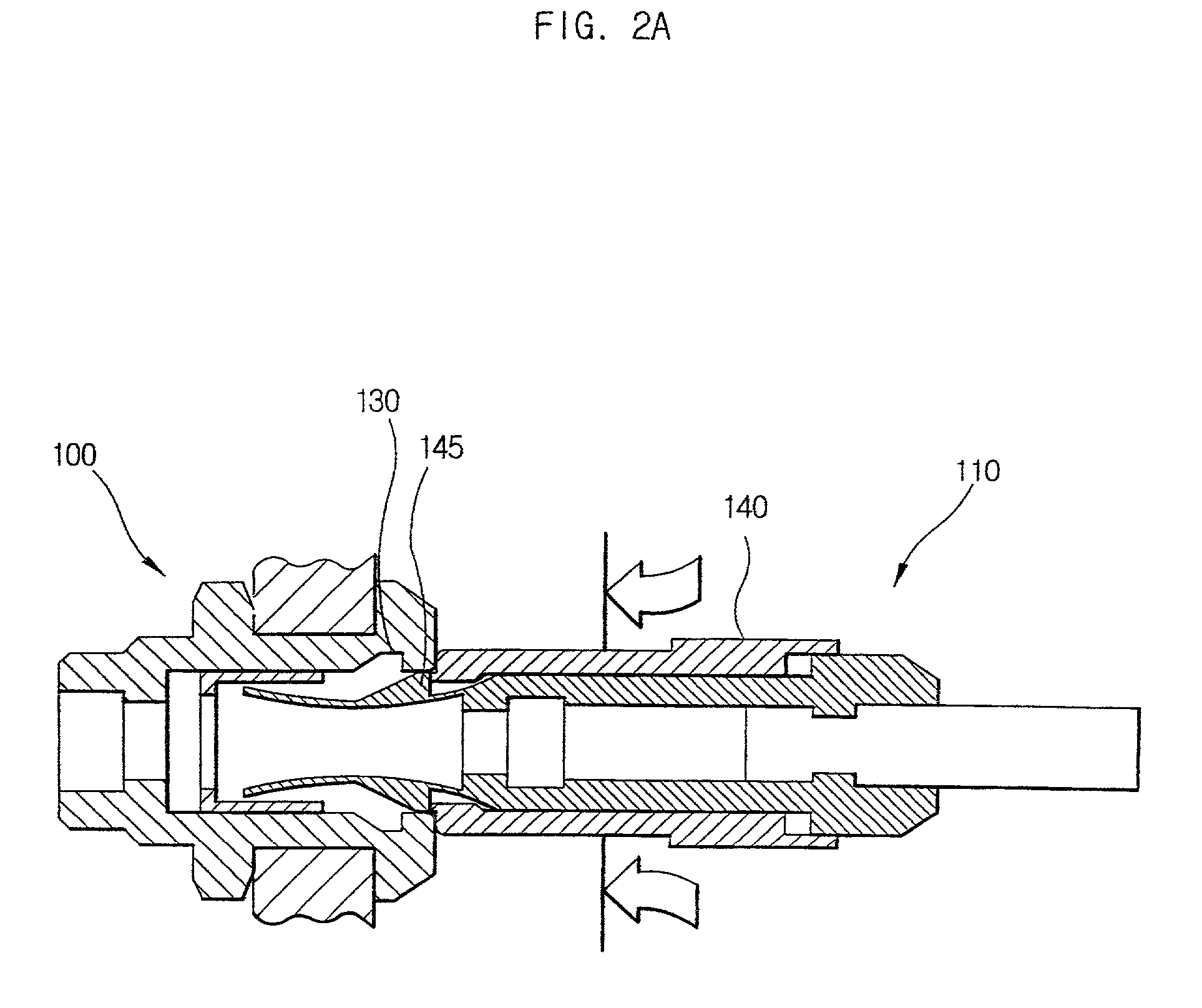
[0036] FIGS. 3A and 3B are cross sectional views for illustrating a connector for electronic appliance of the present invention. More particularly, FIG. 3A is a cross sectional view for showing a socket and a plug before the socket and the plug are combined and FIG. 3B illustrates the socket and the plug after the socket and the plug are coupled together.
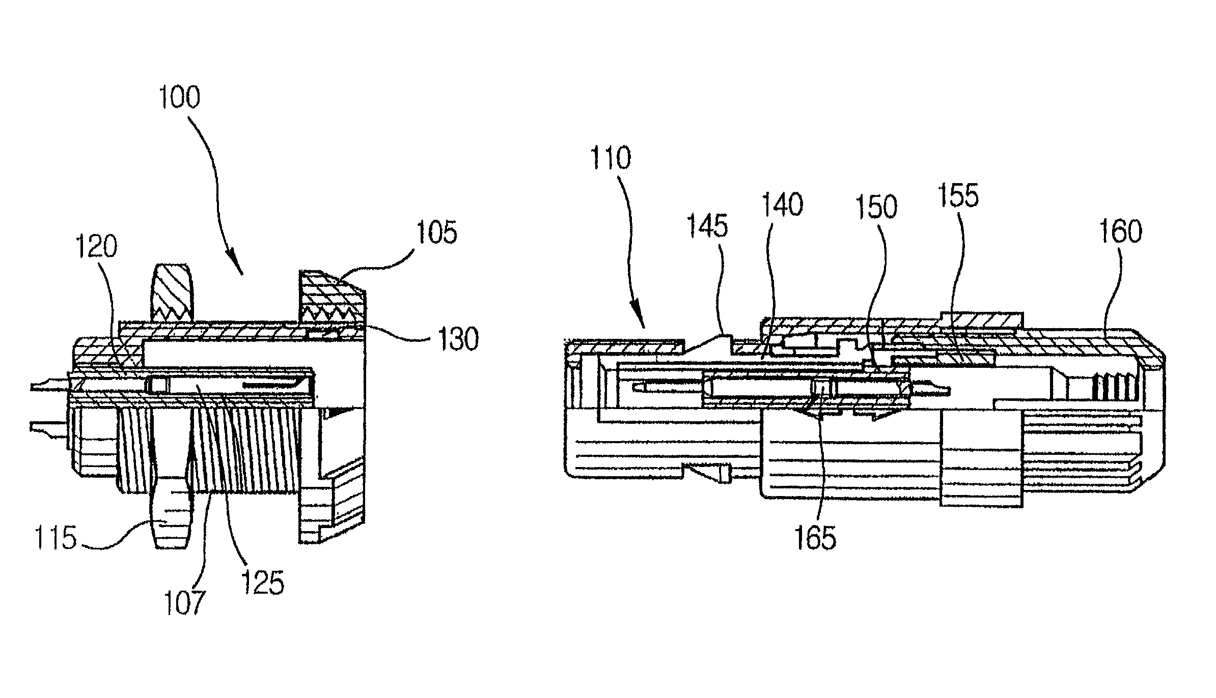
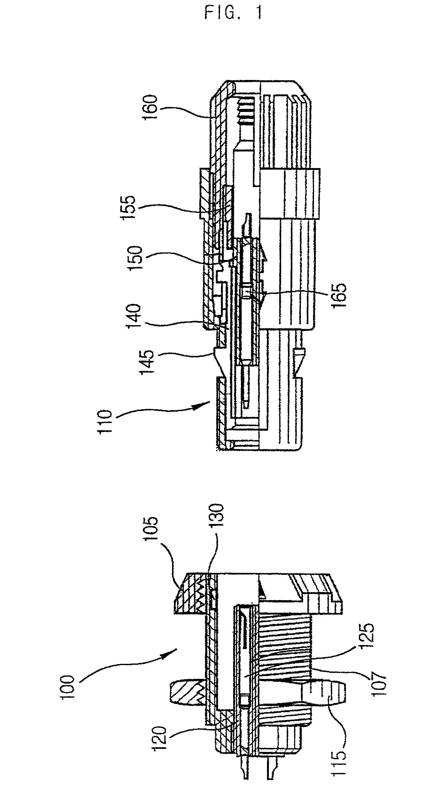
[0037] Referring to FIGS. 3A and 3B, a connector 200 according to one embodiment of the present invention includes a socket 210 and a plug 270.
[0038] The socket 210 has a female contact 240 formed at the central portion of the socket 210 and the plug 270 has a stepped cylindrical shape corresponding to the socket 210. Also, the plug 270 has a male contact 260 formed at the central portion of the plug 270. The male contact 260 corresponds to the female contact 240 of the socket 210.
[0039] The socket 210 further has a first case 220, a first nut 215, a locking groove 230 and a first insulating member 235.
[0040] The first case 220 has...
second embodiment
[0055] FIG. 4 is a cross sectional view for showing a connector according to the present invention.
[0056] In the connector 300 according to the present embodiment, the descriptions of several elements identical to those of the first embodiment will be omitted with an exception to a sliding-type connecting and separating member 380 of the plug 370 and the two locking grooves 330 of the socket 310.
[0057] Referring to FIG. 4, the connector 300 includes the plug 370 having the sliding-type connecting and separating member 380 and the socket 310.
[0058] The sliding-type connecting and separating member 380 includes two balls formed at the outer peripheral portions of the plug 370. The socket 310 also has two locking grooves 330 formed at the inner peripheral portions of the socket 310. Those locking grooves 330 respectively correspond to the balls of the sliding-type connecting and separating member 380.
[0059] When the plug 370 having sliding-type connecting and separating member 380 is i...
third embodiment
[0061] FIG. 5 is a cross sectional view for showing a connector according to the present invention.
[0062] Referring to FIG. 5, the connector 400 according to the present embodiment includes a socket 410 and a plug 470. A sliding-type connecting and separating member 480 having two balls is provided at inner peripheral portions of the socket 410. Two locking grooves corresponding to the balls are formed at outer peripheral portions of the plug 470. Namely, the difference between the second embodiment and the third embodiment is that the sliding type connecting and separating member and the locking grooves are positioned reveresly.
PUM
 Abstract
Description
Claims
Application Information
 - R&D
- Intellectual Property
- Life Sciences
- Materials
- Tech Scout
- Unparalleled Data Quality
- Higher Quality Content
- 60% Fewer Hallucinations
Browse by: Latest US Patents, China's latest patents, Technical Efficacy Thesaurus, Application Domain, Technology Topic, Popular Technical Reports.
© 2025 PatSnap. All rights reserved.Legal|Privacy policy|Modern Slavery Act Transparency Statement|Sitemap|About US| Contact US: help@patsnap.com