Method for forming cut lines in sheet

Inactive Publication Date: 2003-01-02
UNI CHARM CORP
View PDF13 Cites 57 Cited by
  • Summary
  • Abstract
  • Description
  • Claims
  • Application Information

AI Technical Summary

Problems solved by technology

With the edges thus being short, the individual cutting blades are weakened so that they are liable to be worn at their edges and to be folded or broken.
As a result, there will arise a problem that the fiber layer is offset over the sheet.
As a result, the edges of the cutting blades are seriously worn.
More

Method used


Image

  • Method for forming cut lines in sheet
  • Method for forming cut lines in sheet
  • Method for forming cut lines in sheet

Examples


first embodiment

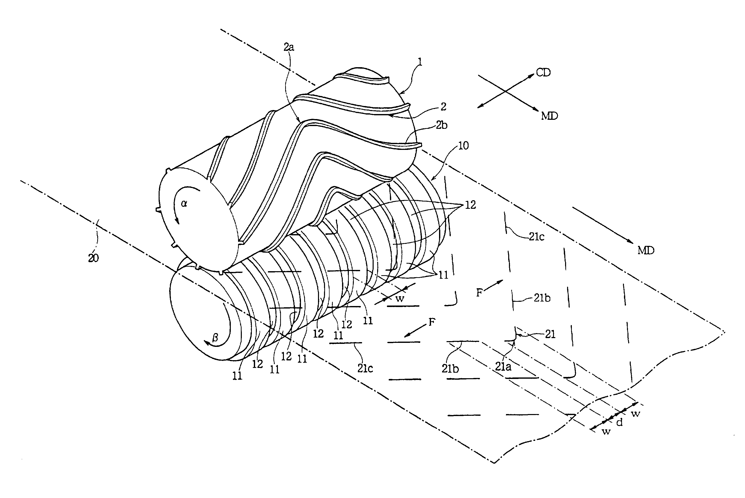
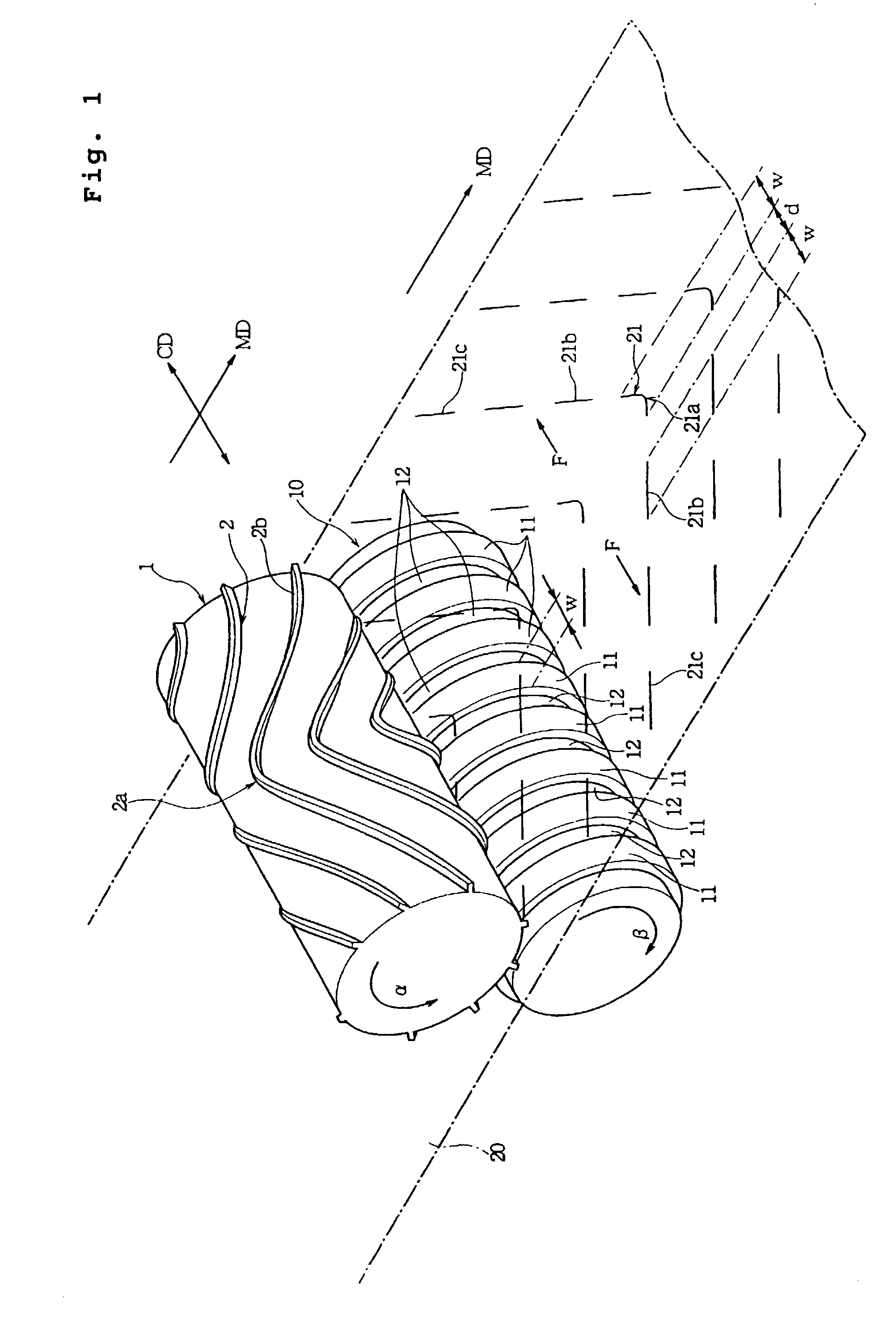
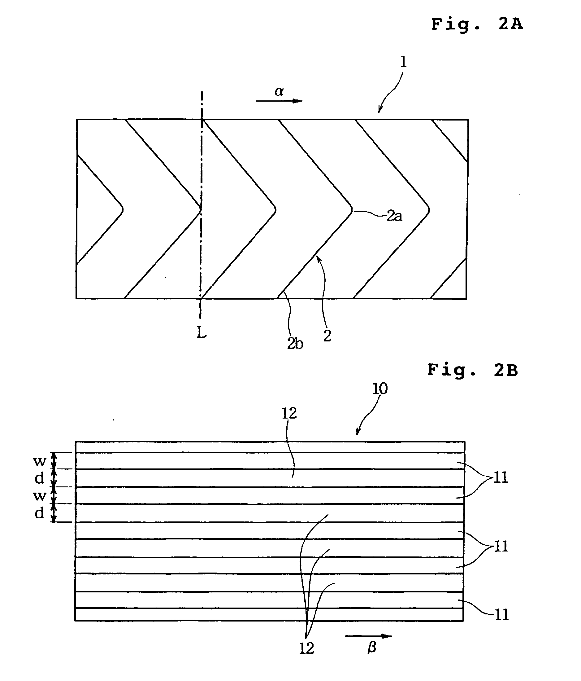
[0044] In FIGS. 1 to 4 showing a method for forming cut lines in a sheet according to the invention: FIG. 1 is a perspective view showing the state in which a sheet is bitten between a cutter roll and an anvil roll; FIG. 2A is a development of the outer circumference of the cutter roll shown in FIG. 1; FIG. 2B is a development of the outer circumference of the anvil roll shown in FIG. 1; FIG. 3 is a top plan view of a cleaning sheet in which the cut lines are formed by that method; and FIG. 4 is a section taken along line IV-IV of FIG. 3.

[0045] FIG. 1 shows a cutter roll 1 and an anvil roll 10. The cutter roll 1 and the anvil roll 10 are made of cemented carbide or tool steel, for example. In this embodiment, a metallic material making the receiving faces 11 of the anvil roll 10 is less hard than that making the cutting blades 2 of the cutter roll 1.

[0046] As shown in FIG. 1, the cutter roll 1 is turned in the direction a whereas the anvil roll 10 is turned in the direction .beta.. ...

second embodiment

[0067] Of FIGS. 5A and 5B and FIG. 6 showing a method according to the invention for forming cut lines: FIG. 5A is a development of the outer circumference of the cutter roll 1; FIG. 5B is a development of the outer circumference of an anvil roll 10A; and FIG. 6 is a top plan view showing a sheet 20B having cut lines.

[0068] The cutter roll 1 shown in FIG. 5A is identical to the cutter roll 1 shown in FIG. 2A to have the generally V-shaped cutting blades 2 formed at the constant interval in the turning direction (or in the direction a). The individual cutting blades 2 are formed continuously without any interruption in the roll axis direction (CD).

[0069] On the outer circumference of the anvil roll 10A shown in FIG. 5B, there are formed the receiving faces 11 of the predetermined width W and the grooves 12 for separating the receiving faces 11 at the spacing d in the roll axis direction. The width size W of the receiving faces 11 in the roll axis direction (CD) is preferably 1 mm or ...

third embodiment

[0078] FIGS. 7A and 7B and FIG. 8 show the invention. The anvil roll 10A shown in FIG. 7B is identical to that shown in FIG. 5B. In a cutter roll 1A shown in FIG. 7A, however, cutting blades 2A, as protruded from the outer circumference, are extended at a right angle with respect to the turning direction (or the direction a) and linearly in the roll axis direction (CD).

[0079] In a cleaning sheet 20C, as shown in FIG. 8, cut lines 21A are formed by the cutter roll 1A and the anvil roll 10A, as shown in FIGS. 7A and 7B. The cleaning sheet 20C shown in FIG. 8 is given a layer structure identical to those shown in FIGS. 3, 4 and 6 by laminating the nonwoven fabric 23 and the fibrous web 24. In the cleaning sheet 20C shown in FIG. 8, a set of cut lines 21A are formed by one cutting blade 2A to extend linearly in the widthwise direction (CD) like a perforated line. Between these sets of the cut lines 21A, there are interposed fused lines 22A extending linearly in the CD to bond the nonwov...


PUM

PropertyMeasurementUnit
Sizeaaaaaaaaaa
Circumferenceaaaaaaaaaa
Hardnessaaaaaaaaaa

Abstract

There is disclosed a cut line forming method including: using a cutter roll (1) having cutting blades (2) protruded on its outer circumference and an anvil roll (10) for receiving the cutting blades; feeding a sheet (20) into the clearance between the cutter roll and the anvil roll; and turning the rolls individually to form cut lines (21) in the sheet. The cutting blades (2) of the cutter roll (10) are formed into a shape of letter "V". The anvil roll has receiving faces (11) of a predetermined width (w) formed at an interval in a roll axis direction. The cutter roll (1) is turned to direct the crests of the V-shape of the cutting blades forward of the turning direction thereby to advance cuts from the side of the crests of the V-shape so that cut lines corresponding to the width size of the receiving faces may be intermittently formed in the sheet along the V-shape.

Description

[0001] 1. Field of the Invention[0002] The present invention relates to a cut line forming method for forming a plurality of cut lines of a predetermined length in a sheet made of paper, a nonwoven fabric, a film, a composite of a nonwoven fabric and a film, a composite of a nonwoven fabric and a fibrous web, a composite of a film and a fibrous web, a composite of a film, a nonwoven fabric and a fibrous web, or the like.[0003] 2. Description if the Prior Art[0004] In the general method for forming the cut lines of a predetermined length in those various sheets, both a cutter roll having a plurality of cutting blades protruded intermittently on the outer circumference for setting the length of the cut lines and an anvil roll having a receiving face for the cutting blades on the outer circumference are used and fed at the clearance inbetween with the sheet and are then turned. During these turns, the sheet is bitten and cut between the cutting blades and the receiving face so that the...

Claims


Application Information

Patent Timeline
IPC IPC(8): B26D7/20B26D1/40B26F1/20
CPCB26D7/20B26D2007/202B26F1/20Y10T83/9408Y10T83/4838Y10T83/0515
Inventor TANAKA, YOSHINORI
Owner UNI CHARM CORP
Why Eureka
Try Eureka