Method for hysteresis compensation in an actuator and a selector fork that is adjustably by this actuator

a technology of selector forks and actuators, applied in the direction of mechanical control devices, process and machine control, instruments, etc., can solve problems such as complicated fastening

Active Publication Date: 2022-11-17
MAGNA POWERTRAIN AG & CO KG
View PDF4 Cites 0 Cited by
  • Summary
  • Abstract
  • Description
  • Claims
  • Application Information

AI Technical Summary

Problems solved by technology

However, it is complicated to fasten the sliding shoes to the steel sheet of the selector fork, since the sliding shoes on such selector forks should be manufactured from slide-promoting material and ...

Method used


Image

  • Method for hysteresis compensation in an actuator and a selector fork that is adjustably by this actuator
  • Method for hysteresis compensation in an actuator and a selector fork that is adjustably by this actuator
  • Method for hysteresis compensation in an actuator and a selector fork that is adjustably by this actuator

Examples


Embodiment Construction

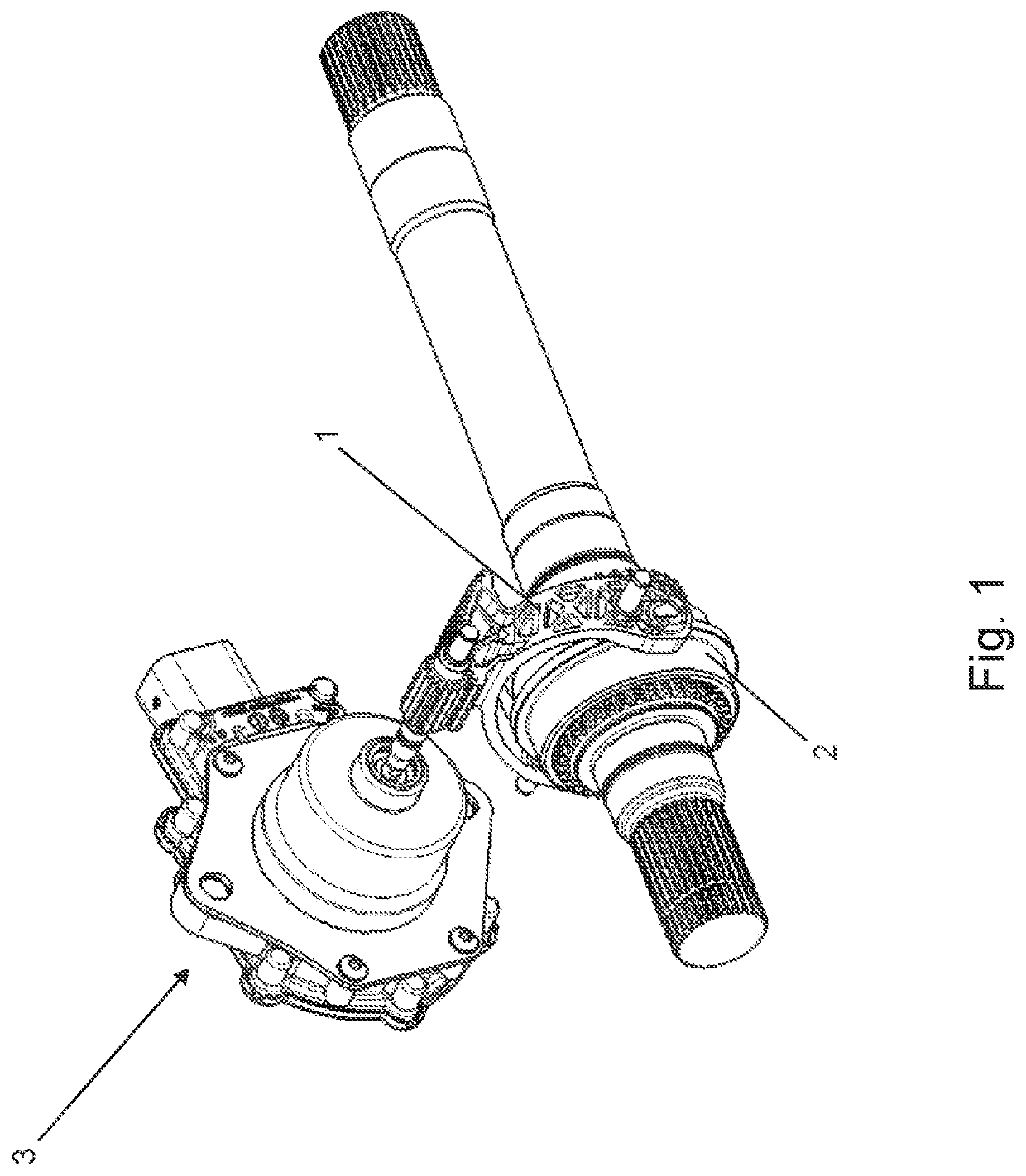
[0028]The method according to the invention serves for hysteresis compensation in an actuator 3 and a selector fork 1 that guides a sliding sleeve 2 (FIG. 1) and is adjustable via the actuator 3. The selector fork 1 can be moved by means of the actuator 3 into two different shift positions, namely a first shift position xDecoup and a second shift position xCoup. The first shift position xDecoup of the selector fork 1 corresponds to a neutral position and the second shift position xCoup corresponds to a gear position. The actuator 3 can, to this end, be actuated into a first position phiDecoup, resulting in the selector fork 1 being moved into the first shift position xDecoup. Furthermore, the actuator 3 can be actuated into a second position phiCoup, resulting in the selector fork 1 being moved into the second shift position xCoup.

[0029]If the selector fork 1 is in a shift position xCoup, xDecoup, it is mechanically released via mechanical releasing of the actuator 3.

[0030]The actua...


PUM


Abstract

A method for hysteresis compensation in an actuator and a selector fork that is adjustable by this actuator and guides a sliding sleeve, by means of a state machine, wherein the selector fork is moved by means of the actuator from a first shift position (xDecoup), namely a neutral position, into at least one second shift position (xCoup), namely a gear position, and vice versa, wherein the position of the actuator (phiAtr, phiCoup, phiDecoup), in the event of a shift request into the neutral position (xDecoup) or into the gear position (xCoup), is corrected on the basis of stored mechanical backlash (phiBL) between the actuator and the selector fork and of a sign (+1, 0, −1) generated by the state machine and associated with the particular shift request.

Description

CROSS-REFERENCE TO RELATED APPLICATIONS[0001]This application claims priority to German Application No. DE 10 2021 204 859.5 filed May 12, 2021. The entire disclosure of the above application is incorporated herein by reference.FIELD OF THE INVENTION[0002]The present invention relates to a method for hysteresis compensation in an actuator and a selector fork that is adjustable by this actuator and guides a sliding sleeve, by means of a state machine.BACKGROUND OF THE INVENTION[0003]This section provides information related to the present disclosure which is not necessarily prior art.[0004]Selector forks are produced largely without machining by forming sheet metal, for example by means of stamping, drawing or pressing or by combinations of these methods. Therefore, the selector forks are able to be produced cost-effectively from sheet metal particular by mass production and are used increasingly frequently. Further structural elements made of steel can be attached easily to the stee...

Claims


Application Information

Patent Timeline
IPC IPC(8): F16H61/10F16H63/32F16H61/28
CPCF16H61/10F16H63/32F16H61/2807F16H2063/328F16H2061/0075F16H63/02F16H61/00F16H2063/325F16H2063/321F16H63/304F16H61/28F16H2061/283
Inventor KOHLBÖCK, MARKUS
Owner MAGNA POWERTRAIN AG & CO KG
Why Eureka
Try Eureka