
Water-abrasive-suspension cutting system

a suspension cutting and water-abrasive technology, applied in the direction of plug valves, valve details, multiple way valves, etc., can solve the problems of reducing cutting performance, refilling abrasive agents, and limited abrasive agent-water ratio, etc., to achieve the effect of continuous operation of the facility

Active Publication Date: 2022-04-19
ANT APPLIED NEW TECH
View PDF53 Cites 0 Cited by
  • Summary
  • Abstract
  • Description
  • Claims
  • Application Information

AI Technical Summary

Benefits of technology

The facility maintains continuous operation by preventing valve clogging and blocking, allowing for higher abrasive agent-water ratios and enhanced cutting force without air entrainment, ensuring reliable and efficient refilling processes.

Problems solved by technology

With regard to water-abrasive injection cutting facilities, although there is not the problem of mixing the abrasive agent with the water at a high pressure since the abrasive agent is not fed until at the exit nozzle, the abrasive agent-water ratio however is very limited with regard to water-abrasive injection cutting facilities and herewith its cutting force.
Furthermore, in the case of water-abrasive injection cutting facilities, entrapped air leads to a reduction of the cutting performance due to the ineffective acceleration of the abrasive agent particles on being sucked into the water jet, as well as to high air components in the cutting jet.
With regard to these facilities, the refilling of the abrasive agent is a technical challenge, since for this the facility must be taken out of operation, the abrasive agent container must be brought into a pressureless state and only then can it be filled.
Due to the particularly high pressures to some extent above 2000 bar, the reliable opening and closing of such lock solutions however is somewhat of a technical challenge.
The abrasive agent can also clog and / or block lock valves.

Method used


Image

  • Water-abrasive-suspension cutting system
  • Water-abrasive-suspension cutting system
  • Water-abrasive-suspension cutting system

Examples


first embodiment

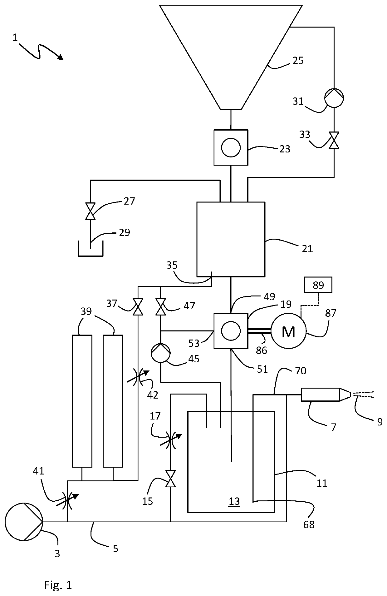
[0056]In the first embodiment which is shown in FIG. 1, the pressure accumulator 39 is charged in pressure immediately from the moment, in which it has discharged itself of pressure. In this case, the high-pressure conduit 5 pressurizes the lock chamber 21 with the residual pressure as well as the pressure accumulator 39. This is particularly advantageous when the charging of the pressure accumulator 39 with pressure is so time-consuming that the refilling throughput rate depends on the pressure charging time of the pressure accumulator 39.

second embodiment

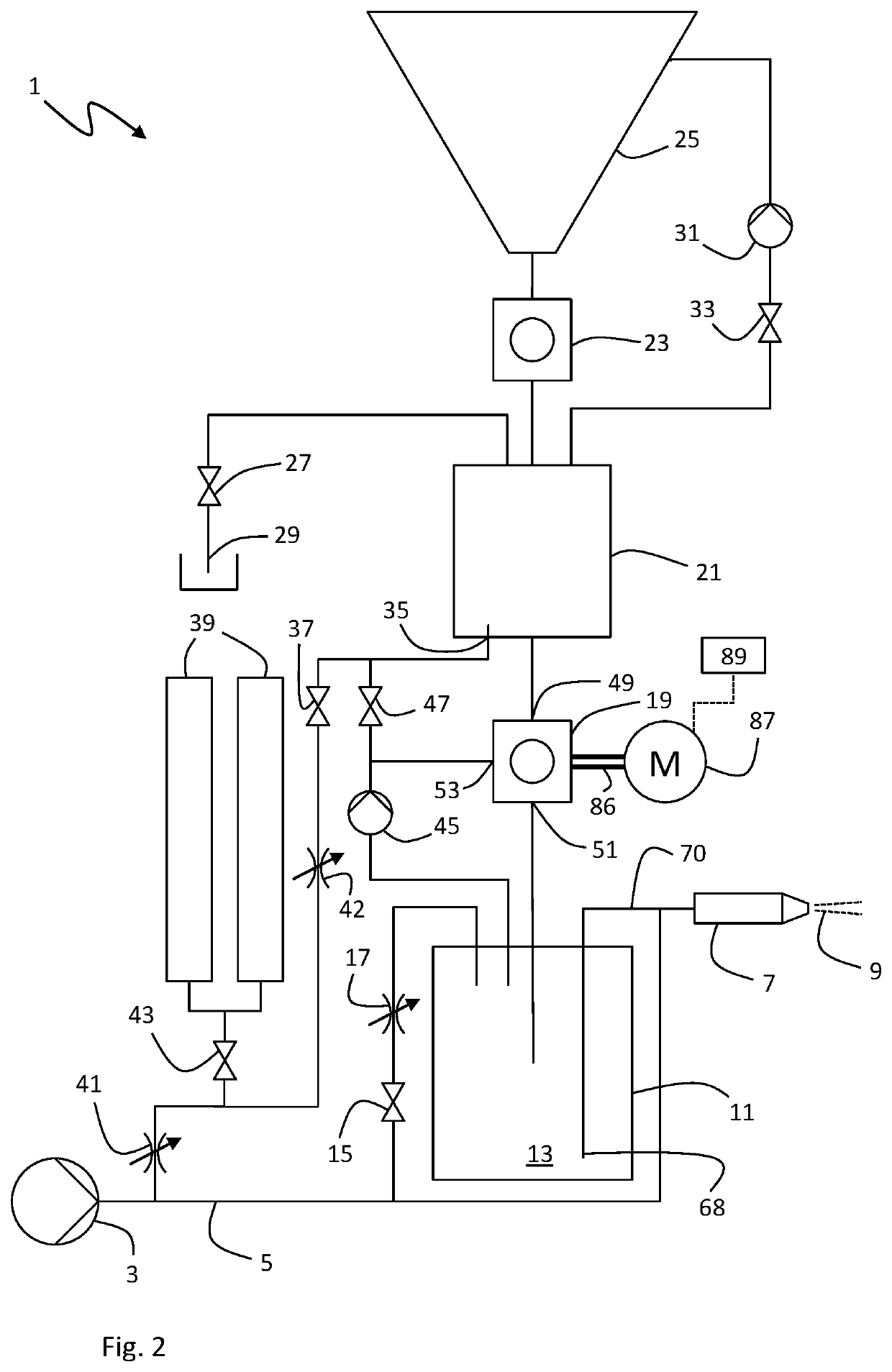
[0057]In the second embodiment which is shown in FIG. 2, the pressure accumulator 39 can be shut off by a pressure accumulator valve 43 in the form of a needle valve. The pressure accumulator valve 43 can be shut off at the moment, in which the pressure accumulator 39 has discharged itself of pressure, in order not to additionally load the high-pressure conduit 5 by the pressurization of the pressure accumulator 38 during the pressurization of the lock chamber 21. Such a loading could cause a pressure drop in the high-pressure conduit 5 which could have a negative influence upon the cutting performance at the exit nozzle 7. For this reason, it is advantageous for the pressure accumulator valve 43 not to open until the lock chamber 21 is completely pressurized and the pressurization valve 37 is closed, so that the pressure accumulator 39 can be charged in pressure from the high-pressure conduit 5 via the throttle 41. In particular, this is advantageous if the pressure charging of the...

third embodiment

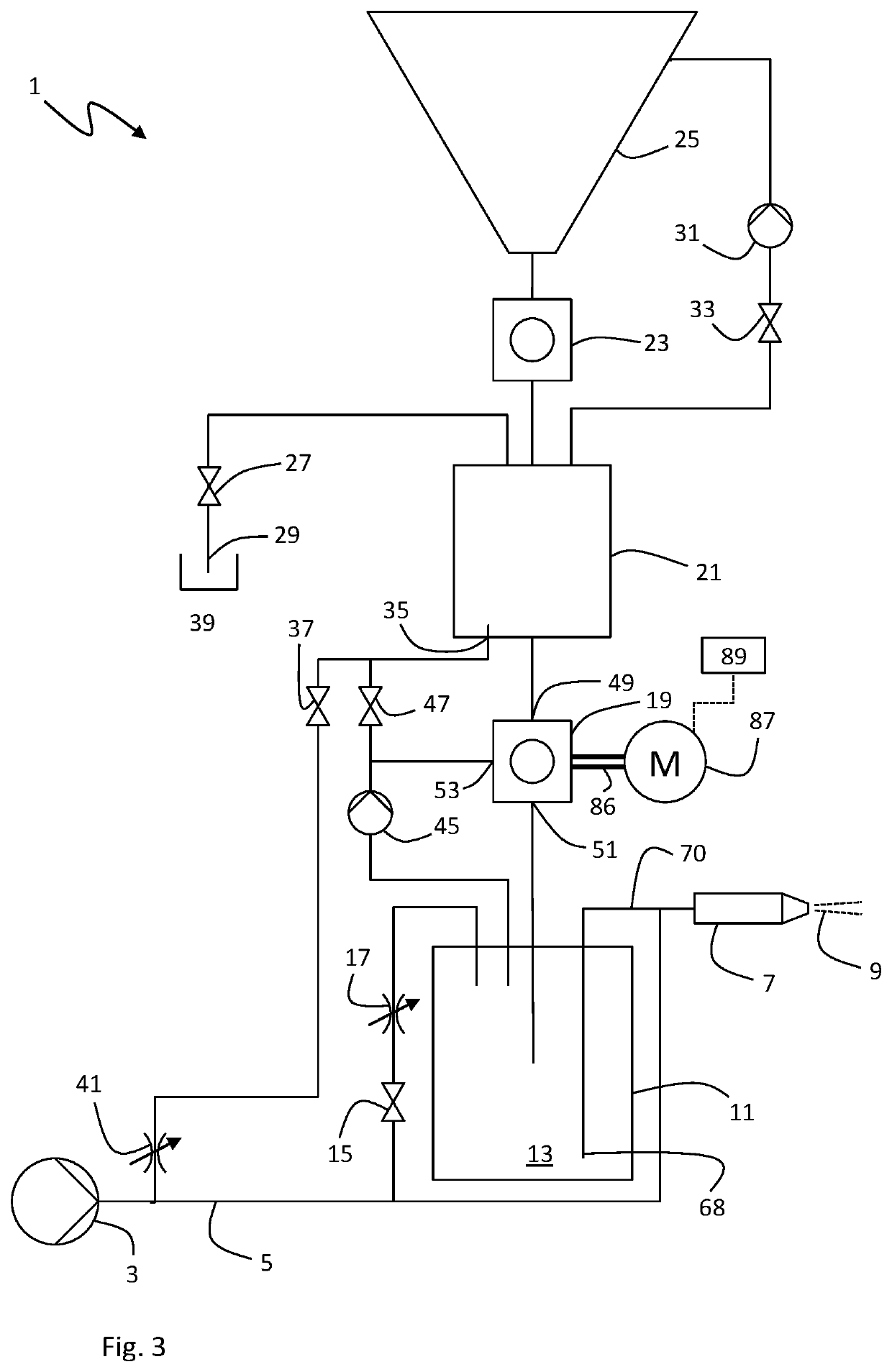
[0058]In a third embodiment according to FIG. 3, one completely forgoes the pressure accumulator 39, and the lock chamber 21 is pressurized exclusively from the high-pressure conduit via the throttle 41. This is advantageous if the high-pressure source 3 for example via a servo pump control can react so quickly to an initial pressure drop and the pump power adapted accordingly, that a large amplitude of the pressure drop does not even occur in the first place. An initial pressure drop can be communicated to the high-pressure source 3 via pressure sensors, so that the high-pressure source 3 can rapidly counter-control a further pressure drop with an increase in the power or a speed increase. The initial pressure drop can already be lessened via the throttle 41, so that at no point in time does a pressure drop which significantly compromises the cutting power occur.

[0059]As soon as the lock chamber 21 has now been completely pressurized, the refilling valve 19 can be opened, so that a...


PUM

PropertyMeasurementUnit
pressuresaaaaaaaaaa
pressureaaaaaaaaaa
pressureaaaaaaaaaa

Abstract

A water-abrasive suspension cutting facility includes a pressure tank (11) for providing a water-abrasive agent suspension (13) which is under pressure, a lock chamber (21), and a refilling valve for refilling abrasive agent into the pressure tank via the lock chamber (21). The refilling valve (21) includes a valve entry (49), a valve exit (51), a valve space (71) which is arranged between the valve entry (49) and the valve exit (51), and a valve body (67) which is located in the valve space (71). The valve entry (49) is connected to the lock chamber (21) and the valve exit (51) to the pressure tank (11). The refilling valve (19) can assume a first closure position, a first open position and a second open position. In the first closure position the lock chamber (21) is fluid-separated from the pressure tank.

Description

CROSS REFERENCE TO RELATED APPLICATIONS[0001]This application is a United States National Phase Application of International Application PCT / EP2017 / 057783 filed Mar. 31, 2017, the entire contents of which are incorporated herein by reference.FIELD OF THE INVENTION[0002]The present disclosure relates to a water-abrasive suspension cutting facility.BACKGROUND OF THE INVENTION[0003]Water-abrasive suspension cutting facilities are used for cutting materials by way of a high-pressure water jet, to which an abrasive agent is added. Water-abrasive suspension cutting facilities are to be differentiated from water-abrasive injection cutting facilities, concerning which the abrasive agent is not introduced into the already greatly accelerated water until or at an exit nozzle. Concerning water-abrasive suspension cutting facilities, the water which is at a high pressure is firstly mixed with the abrasive agent and the water-abrasive suspension is then accelerated in the exit nozzle. With regar...

Claims


Application Information

Patent Timeline
Patent Type & Authority Patents(United States)
IPC IPC(8): B24C1/04B24C7/00F16K11/087F16K5/20F16K27/06F16K31/04
CPCB24C1/045B24C7/0007F16K5/201F16K11/087F16K11/0873F16K27/067F16K31/042F16K37/0025F16K5/06B24C7/0023B24C7/0084B24C1/04
Inventor LINDE, MARCO
Owner ANT APPLIED NEW TECH
Learn More