
Inhaler

a technology of inhaler and cartridge, which is applied in the field of inhalers, can solve the problems of inconvenient use for users, damaged and degraded fixed parts of cartridges, cumbersome and time-consuming operation to repair the ejection head, etc., and achieve the effect of accurate and durable operation

Inactive Publication Date: 2012-09-18
CANON KK
View PDF17 Cites 1 Cited by
  • Summary
  • Abstract
  • Description
  • Claims
  • Application Information

AI Technical Summary

Benefits of technology

The present invention provides an inhaler that allows for easy removal and accurate operation of a cartridge with an ejection head and reservoir. The inhaler includes a cartridge mounting section on the inhaler body, a junction forming section on the cartridge, a cartridge fixing member, and two electric connection sections that connect to the ejection head. The cartridge is fixed on the inhaler body using the cartridge fixing member, which ensures reliable electrical connection between the cartridge and the inhaler body. The design of the electric connection sections prevents wear and tear, prolongs the service life of the inhaler, and reduces the frequency of parts replacement. The overall operation of the inhaler is easy, and the contacts are visually recognizable.

Problems solved by technology

In other words, a nebulizer is not a particularly convenient system from the user's viewpoint.
If an ejection head is incorporated into the main body from the beginning and develops a problem, it is a cumbersome, costly and time-consuming operation to repair the ejection head.
If they have problems in terms of structure and / or construction for realizing such functions simultaneously including establishing a plurality of contacts, the fixed parts of the cartridge can be damaged and degraded while the electric connection terminals may be worn and degraded.
While the linking and contacting units can be isolated to avoid the above identified problem, the number of operations that the user needs to perform will then be increased, and one or more additional mechanisms and spaces are required to consequently make the main body more complex and larger.

Method used


Image

  • Inhaler
  • Inhaler
  • Inhaler

Examples


example 1

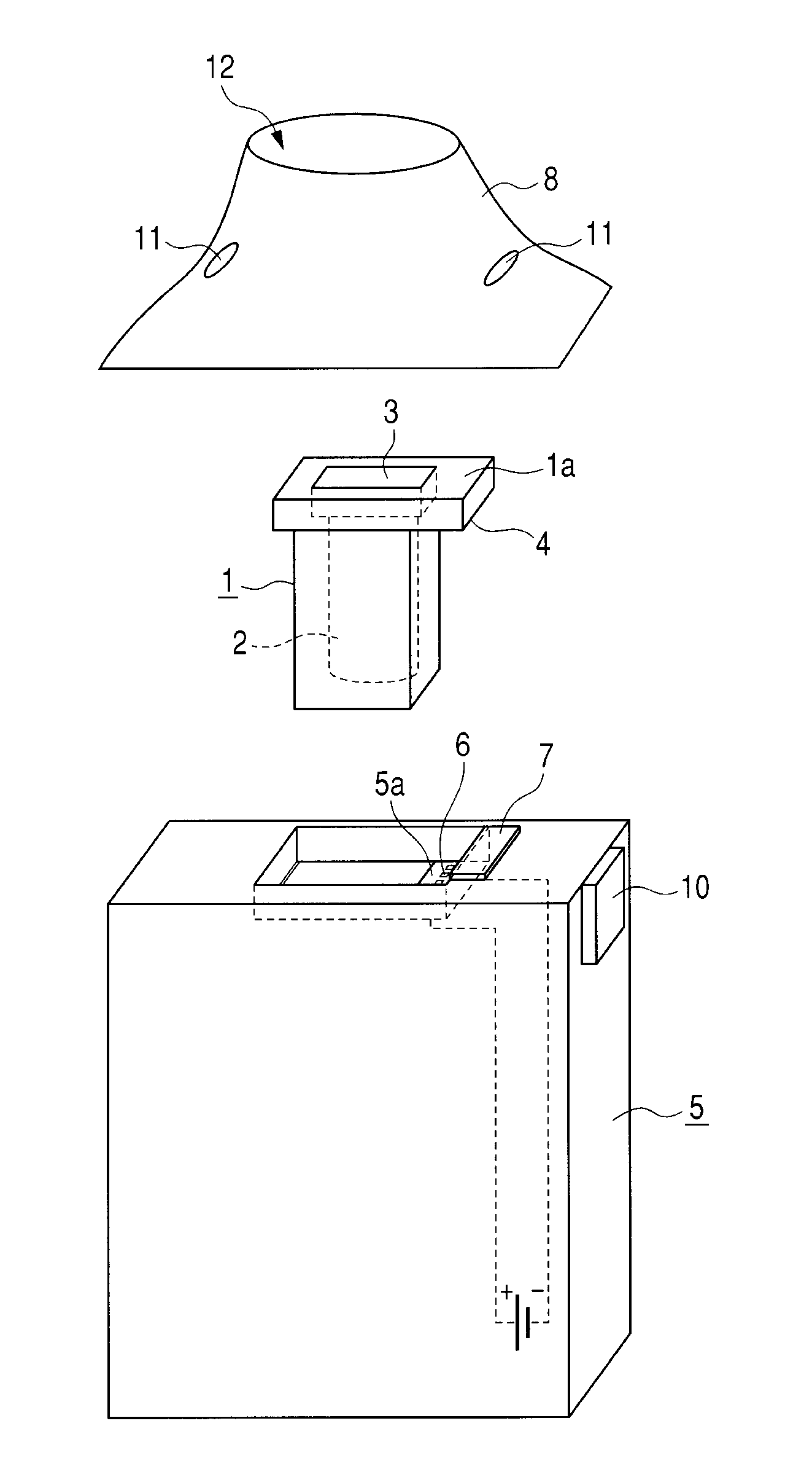
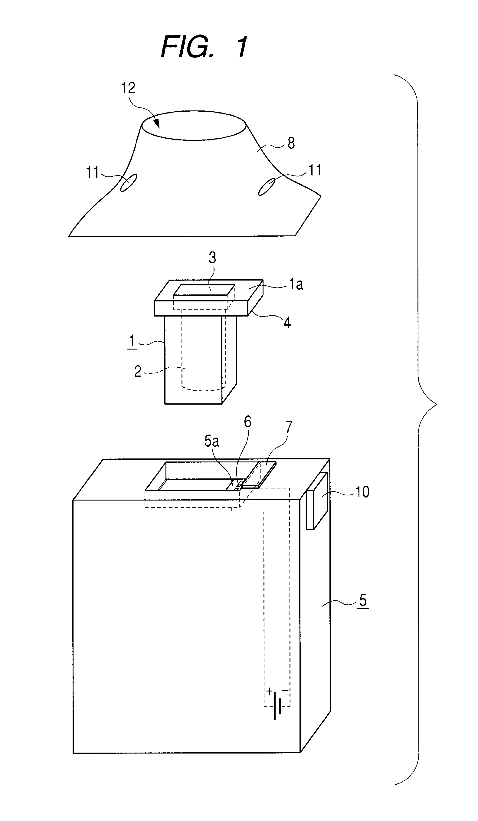
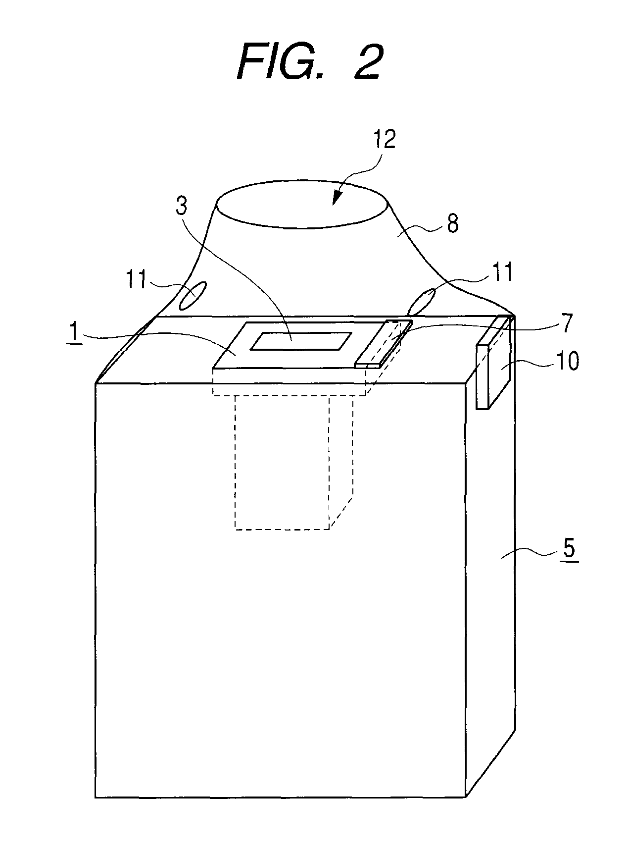
[0060]FIG. 1 through FIGS. 5A and 5B schematically illustrate the first embodiment of inhaler according to the present invention. The cartridge 1 includes a reservoir 2, an ejection head 3 and a first electric connection section 4 for supplying power. As illustrated in FIG. 3A, the reservoir 2 and the ejection head 3 communicate with each other by way of a communication needle 2a in the cartridge so that medicine is supplied from the reservoir 2 to the ejection head 3.

[0061]An inhalation piece 8 to be used by the user to inhale medicine is mounted to the inhaler body 5 while the cartridge 1 is mounted in the inside of the inhalation piece 8.

[0062]As illustrated in FIGS. 5A and 5B, the inhaler body 5 has a cartridge mounting section 5a on which the cartridge 1 is mounted and a second electric connection section 6 and a restitutive member, which is described above, are arranged there. As the cartridge 1 is rigidly secured to the inhaler body 5 by means of the cartridge fixing member 7...

example 2

[0066]FIGS. 6 and 7 schematically illustrate the second embodiment of inhaler according to the present invention. The second embodiment of inhaler includes a cartridge fixing member 27 having an opening 27a so as to surround the ejection surface of cartridge 1 and rigidly secure the cartridge 1 to the inhaler body 5. The cartridge 1, the inhaler body 5 and the inhalation piece 8 of this embodiment are the same as their counterparts of the first embodiment and hence denoted respectively by the same reference symbols and will not be described any further.

[0067]The cartridge fixing member 27 is supported at an end thereof by the inhaler body 5 so as to be able to turn at rotary section 23. The cartridge 1 is mounted on the inhaler body 5 and then the cartridge fixing member 27 is turned onto the cartridge to rigidly secure the cartridge in place. Then, the cartridge fixing member 27 contacts the cartridge 1 near the ejection head 3. Thus, the cartridge 1 is rigidly secured by the cartr...

example 3

[0069]FIGS. 11 and 12 schematically illustrate the third embodiment of inhaler according to the present invention. The inhaler of this embodiment is provided with a junction forming member (junction forming section) 45 that is movable relative to the inhaler body 5 so as to make it possible to release the electric connection between the cartridge 1 and the inhaler body 5 without removing the inhalation piece 8 and the cartridge 1. With this arrangement, the electric connection between the cartridge 1 and the inhaler body 5 can be released to prevent administration of medicine from taking place even while the cartridge 1 is rigidly secured to the inhaler body 5 so as to prevent the inhaler from unintentionally operating by error and improve the safety of the inhaler.

[0070]The junction forming member 45 that is movable relative to the inhaler body 5 is provided with a second electric connection section 46 and the second electric connection section 46 at the side of the inhaler body is...


PUM


Abstract

A cartridge having an ejection head for ejecting medicine and a reservoir as integral parts thereof is provided with an electric connection section on a lower surface of a junction forming section thereof to be brought into contact with an inhaler body. As the cartridge is put into the inhaler body and secured to the latter by means of a cartridge fixing member, the electric connection section of the cartridge is brought into contact with an electric connection section arranged on a top surface of a cartridge mounting section of the inhaler body to establish electric connection between the cartridge and the inhaler body.

Description

BACKGROUND OF THE INVENTION[0001]1. Field of the Invention[0002]The present invention relates to an inhaler for ejecting medicine as liquid droplets and causing the user to inhale it.[0003]2. Description of the Related Art[0004]There are various methods of administering medicine to a patient's body including oral administration, injection by needle, application to the exterior of the body, and the use of a patch, and various devices and systems have been developed for each of these methods. Additionally, many electric devices have been developed as medical equipment as a result of the advancement of science and technology in recent years to make it possible to realize what has been difficult to achieve by mechanical means.[0005]Many varieties of electrical medical equipment are diagnostic devices, while devices for administering medicine also exist, one example being nebulizers. The nebulizer has a vibrator as source of atomization of medicine and electric power is required for it a...

Claims


Application Information

Patent Timeline
Patent Type & Authority Patents(United States)
IPC IPC(8): A61M11/00
CPCA61M11/005A61M11/041A61M15/0085A61M11/042A61M15/025A61M2016/0021A61M2016/0027A61M2205/8206A61M2205/8262
Inventor SUGITA, MASARUKOMATSU, HIROSHIWADA, HIROYUKIFUKUMOTO, YOSHIYUKI
Owner CANON KK
Learn More