Drop forging method and forging device for carrying out said method

a forging method and a technology of forging devices, applied in the field of drop forging methods, to achieve the effects of greater dimensional accuracy, better surface, and greater length

Inactive Publication Date: 2012-02-14
KNIPEX WERK C GUSTAV PUTSCH
View PDF17 Cites 0 Cited by
  • Summary
  • Abstract
  • Description
  • Claims
  • Application Information

AI Technical Summary

Benefits of technology

[0008]With regard to the method, the stated object is achieved first and foremost in the case of the subject matter of claim 1, it being provided that, for every hammer blow, a part is accommodated in a plurality of impressions, with symmetrical distribution between occupied and unoccupied impressions with regard to loading of the ram, the parts being respectively gripped during shaping by the forging gripper, and after every hammer blow a successive displacement of the parts into a further impression being performed, with a part being removed from the final impression or the last impression that is occupied by a part before the final impression, and the blank being placed into the first impression to be occupied. It is preferred that, for every hammer blow, a part is accommodated in each impression, which part is respectively gripped during the shaping by the forging gripper and after every hammer blow is successively displaced into the adjacent impression toward the final impression. In this process, a part is in each case also removed from the final impression and a further part is placed into the first impression. However, even with the method described here, it is possible, as explained in principle for a forging press in the already cited DE 31 29 482 C2, always to skip certain impressions, including in an alternating manner, so that all the impressions are occupied in a specific rhythm, but not simultaneously; this while paying attention to the most uniform loading possible, as desired with regard to a ram, to keep the guides in good condition. It is pertinent that according to the method described here, the hammer is always loaded virtually uniformly. This not only results in less loading of the guides, but also has advantageous effects on the quality of the forged piece. The method is here carried out in a way that is known in principle to this extent, with the forged pieces being constantly gripped. As a result of the described uniform loading of the forging hammer, not only are the guides found to become less worn, but also the forging offset on the forged pieces is not increased in comparison with known methods, but even generally reduced.
[0009]The described method is preferably suitable for forging forged parts such as the halves of pliers. In principle, however, it is also suitable for other forged parts; in particular for such parts as have a greater length than width. These may, for example, also be parts such as connecting rods or camshafts.
[0011]The forging device may still be constructed in the tried-and-tested manner. By occupying the impressions with parts in a symmetrical manner with regard to the loading, or occupying all the impressions with parts, the guides are uniformly loaded. During the return movement of the ram after each hammer blow, the parts lying simultaneously in all the impressions, apart from a part lying in the final impression or the last impression that is occupied before the final impression, are transported at the same time into the adjacent or next-provided impression in the direction of passing through. The die may form at least two impressions of the same form one adjacent the other. Furthermore, the die having the impressions positioned one adjacent the other may have a different alignment in relation to the connecting line of the guide pillars. In particular, there are two possibilities for this. One possibility is that the impressions are disposed one adjacent the other in a connecting line of the guide pillars. On the other hand, the impressions may also be disposed in a series one adjacent the other transversely in relation to the connecting line of the guide pillars. An advantageous configuration is distinguished by providing a transporting device for the parts to be placed into the first impression and / or to be removed from the final impression, with a transporting direction parallel to the direction of passing through. This alignment allows the transporting device for introducing and / or discharging the parts to reach right up to the forging device and allows the transporting device to have in the region of introduction and / or discharge a heating system for heat-treating the parts. To allow the parts to be moved from one impression into the other, the die has a conveying mechanism for raising, conveying and setting down the parts from impression to impression by engaging opposite end regions of the parts. This conveying mechanism is coordinated with the operating mode of the ram, so that a transporting rhythm of the parts that is synchronized with the forging frequency can be obtained.
[0012]Independently of whether all the impressions or only some of the impressions are occupied with a part, in a symmetrical manner, for every hammer blow, it is preferably provided with regard to the transporting device that a forging and transporting gripper is associated with every impression irrespective of the occupation with each hammer blow.
[0013]With regard to the tool costs and the mode of operation, it proves to be of advantage for the forging and / or transporting grippers to be disposed outside a base area of the die. Both the die and the forging and / or transporting grippers represent modules that are independent of one another, so that each can itself be optimally configured. The use of a forging hammer instead of a forging press brings the advantage of low-cost construction of the forging device. In particular, use of a drop hammer as the hammer is commended. This means that, when there is movement of the ram toward the forged piece, acceleration due to gravity takes effect, while raising takes place by means of a lifting member. According to the invention, the hammer may be a counterblow hammer. In this case, the lower ram and upper ram move counter to each other, so that losses of energy due to impact and propagation of the impact in the floor are avoided entirely. The forging and transporting grippers would then have to be disposed at an appropriate level to be associated with the forging tools. The counterblow hammers may even help to simplify the gripping and conveying mechanism, because they offer more space. Such counterblow hammers are of advantage in particular for the forging of crankshafts. Also to be emphasized is the fact that the forged part is constantly gripped during forging, whether by the forging gripper or the transporting gripper. If this gripping takes place by the transporting gripper, the latter even performs a dual function. With regard to its association with the hammer, advantages are obtained in that the guide pillars have at the level of the lower die a recess facing the die for receiving the forging and / or transporting grippers. Moreover, the grippers are configured in such a way that the geometry of the gripping ends, changing during a forging blow, or their alignment, can be taken into account. For this purpose, the forging grippers may for example have pivotally suspended gripping heads or resiliently yielding gripping heads. Up to a certain extent, slipping of the blanks in the gripping ends may also be tolerated. Finally, it must also be emphasized that the forging and / or transporting grippers may be formed in such a way that they are hammer-resistant. On account of this, it is of advantage that the forging and / or transporting grippers move in concert with the movement of the forging hammer with every forging blow.

Problems solved by technology

Troublefree implementation of the method results from the fact that the transporting rhythm of the parts is synchronized with the forging frequency.

Method used


Image

  • Drop forging method and forging device for carrying out said method
  • Drop forging method and forging device for carrying out said method
  • Drop forging method and forging device for carrying out said method

Examples


first embodiment

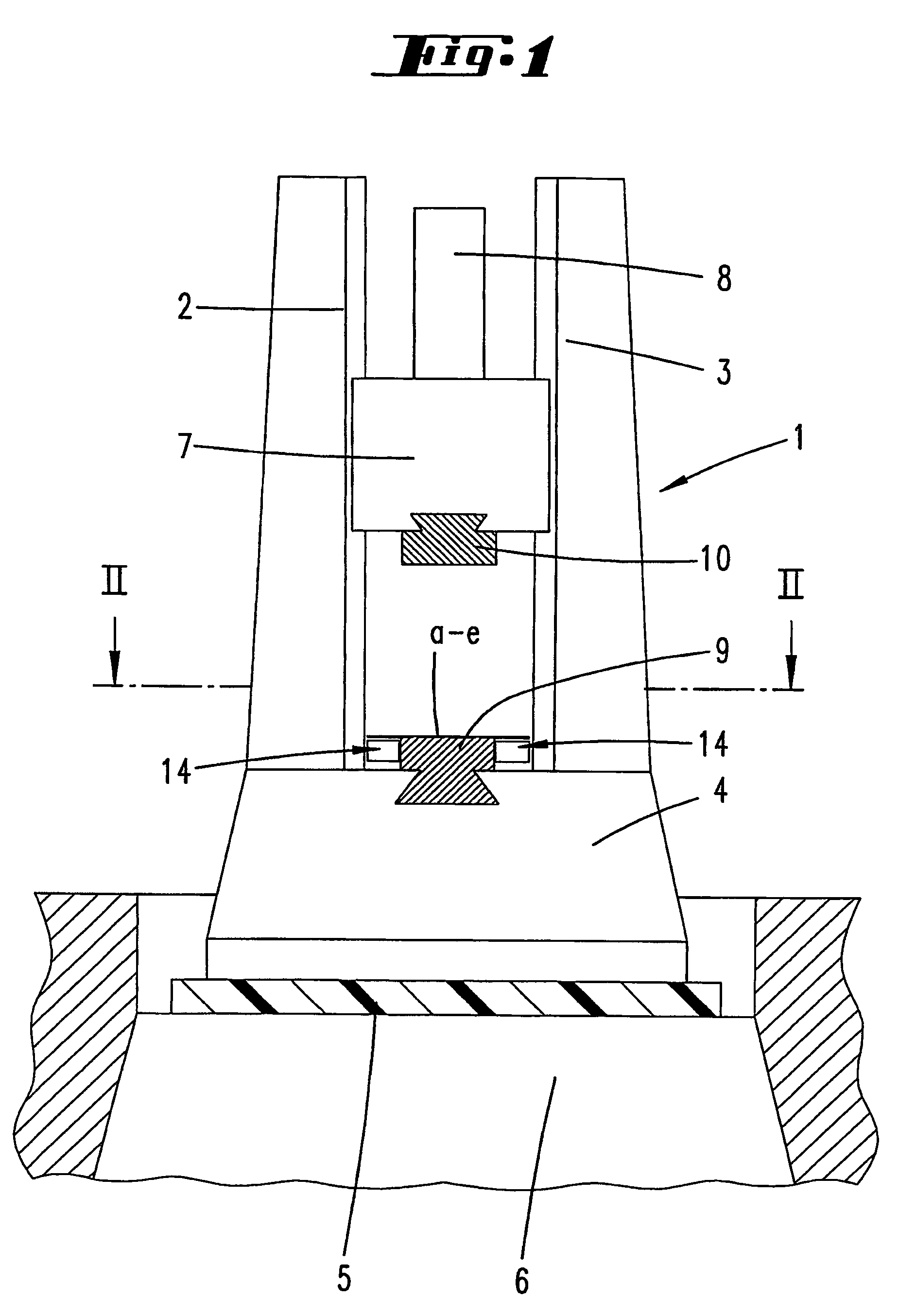
[0026] as shown in FIGS. 1 to 4, the forging device for carrying out the method is designated by the number 1. The forging device 1 has two guide pillars 2, 3, disposed parallel to each other. The latter extend from an anvil block or a base plate 4, which for its part is supported on a foundation 6 by means of an intermediate layer 5.

[0027]The guide pillars 2, 3 accommodate between them a ram 7, which can be moved in the vertical direction and is engaged by a drive 8.

[0028]Between the pillars 2, 3, the base plate 4 carries a lower die 9, which can be secured there by means that are not represented. Opposite the lower die 9, the ram 7 is provided on its underside with an upper die 10.

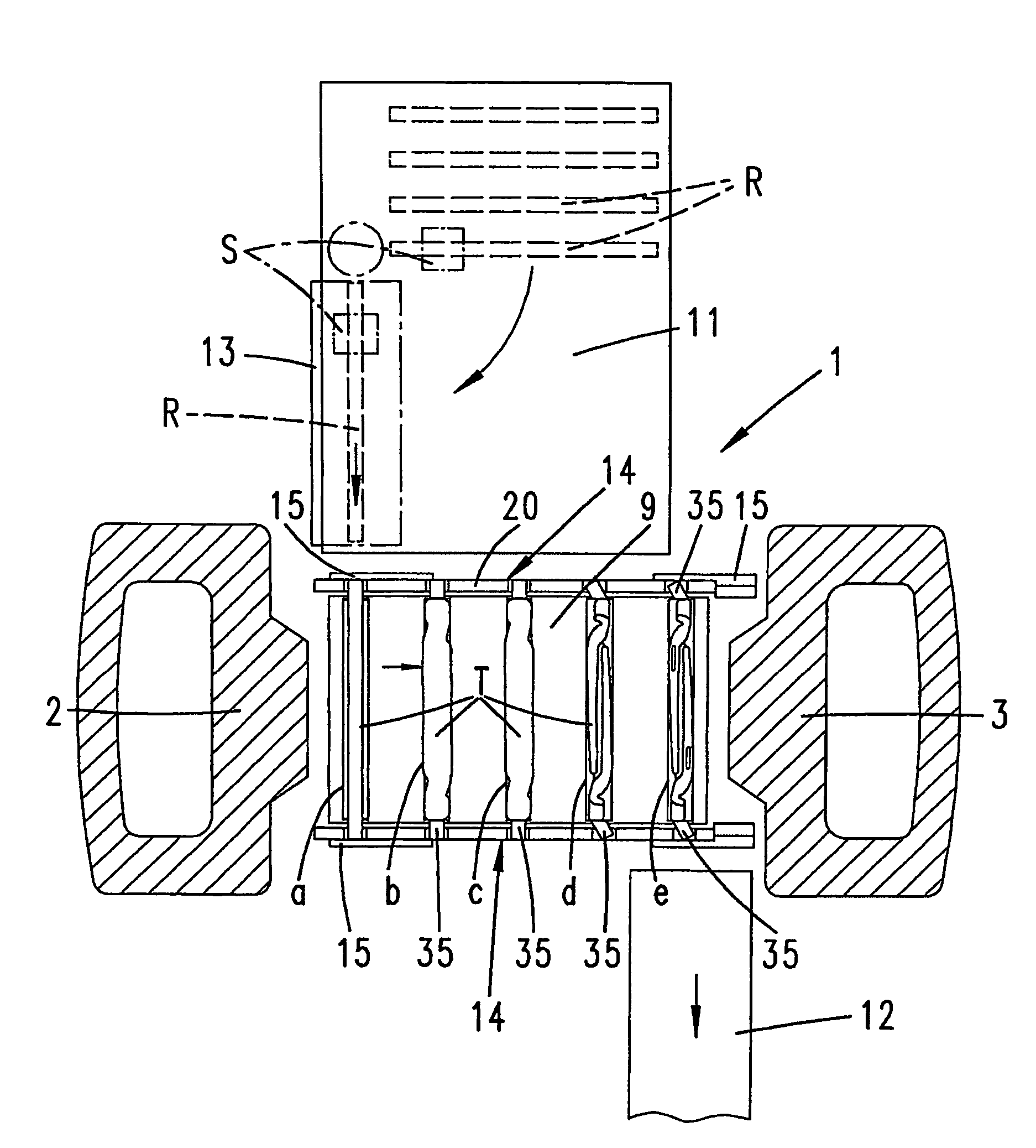
[0029]The die 9 has a rectangular outline and forms on its upper side a plurality of impressions a, b, c, d and e, positioned one adjacent the other. The impression a is the first impression and the impression e is the final impression. The impressions a to e serve for accommodating parts T to be shaped....

second embodiment

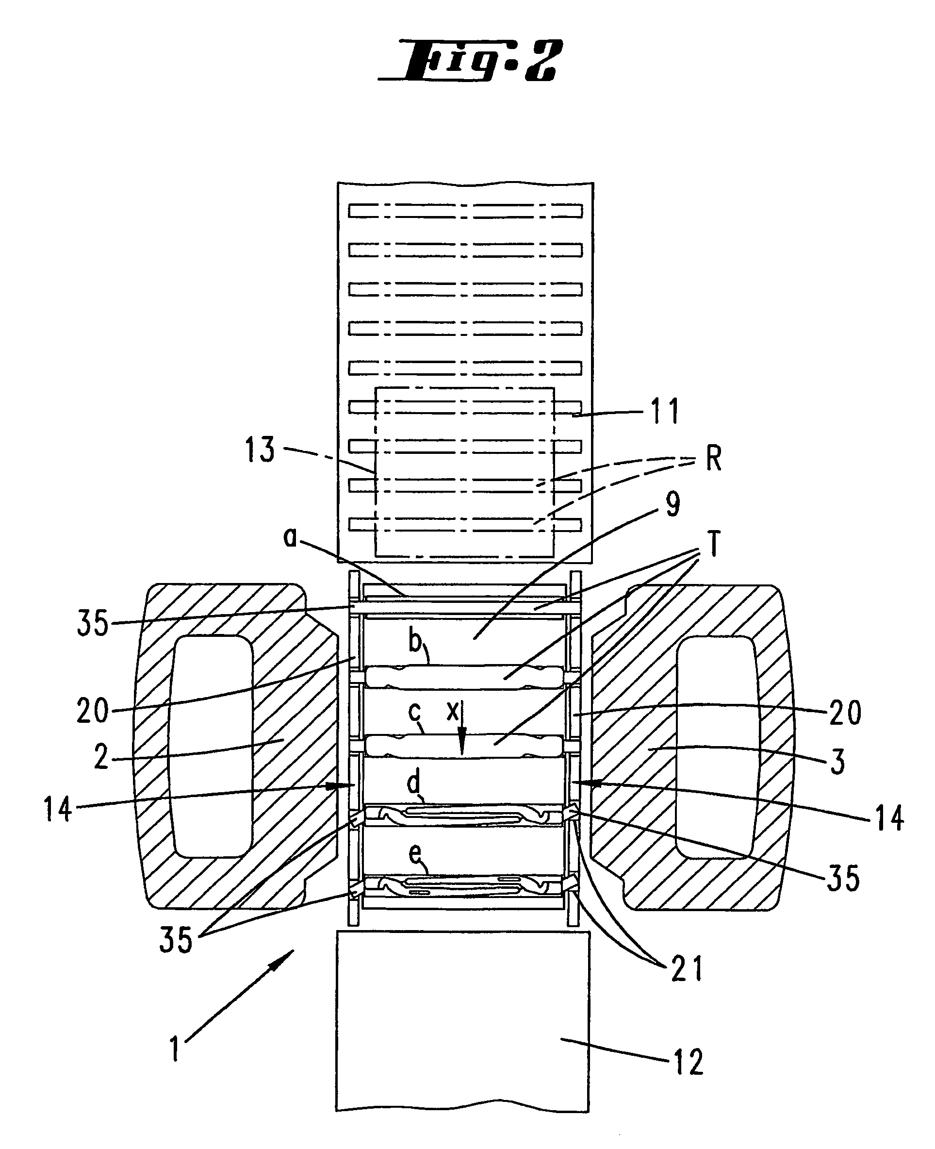
[0035] as shown in FIG. 5, the same components have the same reference numerals. As a departure, the impressions a to e of the die 9′ are now disposed one adjacent the other in a connecting line of the guide pillars 2, 3. This means that the parts accommodated by the impressions are successively displaced on this connecting line during the forging.

[0036]A transporting mechanism 11 similar to in the case of the previous embodiment is then provided. To allow the first blank R in the conveying direction to be transferred as intended to the first impression a, a turning station S is associated with the transporting mechanism 11, which station in each case turns the corresponding blank R through 90° in accordance with the forging frequency and allows it to be pushed into the first impression a. Also provided in this version is a heating system 13, by means of which the blanks delivered to the forging device 1 are brought to the requisite temperature.

[0037]Also represented in this version...

third embodiment

[0042] as shown in FIGS. 8 to 10, the same components have the same reference numerals.

[0043]As a departure from the first embodiment, forging grippers 28 and transporting grippers 29, forming a conveying mechanism 22, are now provided on both sides of the lower die 9. Furthermore, the guide pillars 2, 3 have level with the lower die 9 a recess 30 facing the latter for receiving the forging and transporting grippers 28, 29. The latter are formed in such a way that they are hammer-resistant and therefore move in concert with the forging device 1, which is configured as a forging hammer, with every forging blow. As also in the case of the first embodiment, the hammer is a drop hammer. As in the case of the first embodiment, the longitudinal extent of the impressions a to e then runs in a transversely directed manner in relation to the longitudinal sides of the die 9. Two transporting bars 31, 32, which are disposed one above the other and for their part are carriers of the transportin...


PUM

PropertyMeasurementUnit
frequencyaaaaaaaaaa
timeaaaaaaaaaa
forging frequencyaaaaaaaaaa

Abstract

The invention relates a drop forging method by means of a forging device provided with a hammer and a forging die, wherein a part placed in the forging die is shaped with a hammer blow, several engravings are formed in the die, a blank is initially inserted into the first engraving and said blank is moved along the other engravings to the last engraving, and then said blank picked up during shaping by a forging gripper. In order to obtain an optimum operating mode, the invention is characterized in that the part is received in a plurality of engravings with each hammer blow. In order to obtain a symmetrical distribution of the hammer load between occupied and non-occupied engravings, the parts are gripped respectively during shaping by the forging grippers. After each hammer blow, a successive displacement of the parts is carried out in the other engravings by removing the part from the last engraving or from the last but one by an engraving occupied by a part and a blank is inserted in the first engraving to be occupied.

Description

CROSS-REFERENCE TO RELATED APPLICATIONS[0001]The present application is a continuation of pending International patent application PCT / EP2004 / 053189 filed on Dec. 1, 2004 which designates the United States and claims priority from German patent application Nos. 10 2004 028 378.8 filed Jun. 11, 2004 and 103 56 258.3 filed Dec. 1, 2003, the contents of which are incorporated herein by reference.FIELD OF THE INVENTION[0002]The invention relates to a drop forging method, with a forging device having a ram and a die, a part lying in the die being shaped by a hammer blow, a plurality of impressions also being formed in the die, and a blank first being placed into a first impression and subsequently passing successively through further impressions to a final impression, and furthermore the part being gripped during the shaping by a forging gripper.BACKGROUND OF THE INVENTION[0003]During forging, it has long been the custom to hold the part to be forged by means of gripping tongs. Even when...

Claims


Application Information

Patent Timeline
Patent Type & Authority Patents(United States)
IPC IPC(8): B21J13/10B21J9/02B21J13/08
CPCB21J9/022B21J13/08
Inventor LORBACH, WOLFGANG
Owner KNIPEX WERK C GUSTAV PUTSCH
Why Eureka
Try Eureka