Rotary facial seal and bearing assembly with plastic ring

Inactive Publication Date: 2003-01-09
POLYMER SEALING SOLUTIONS
View PDF1 Cites 52 Cited by
  • Summary
  • Abstract
  • Description
  • Claims
  • Application Information

AI Technical Summary

Problems solved by technology

In aggressive high pressure and velocity environments such prior seals do not adequ

Method used


Image

  • Rotary facial seal and bearing assembly with plastic ring
  • Rotary facial seal and bearing assembly with plastic ring
  • Rotary facial seal and bearing assembly with plastic ring

Examples


Embodiment Construction

of Thrust Bearing

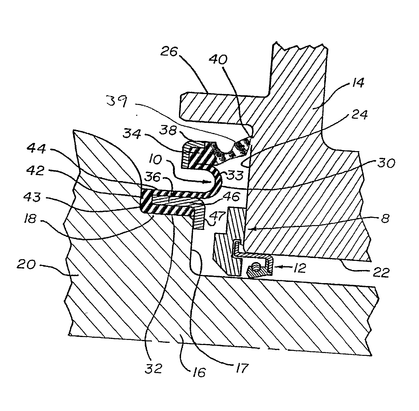
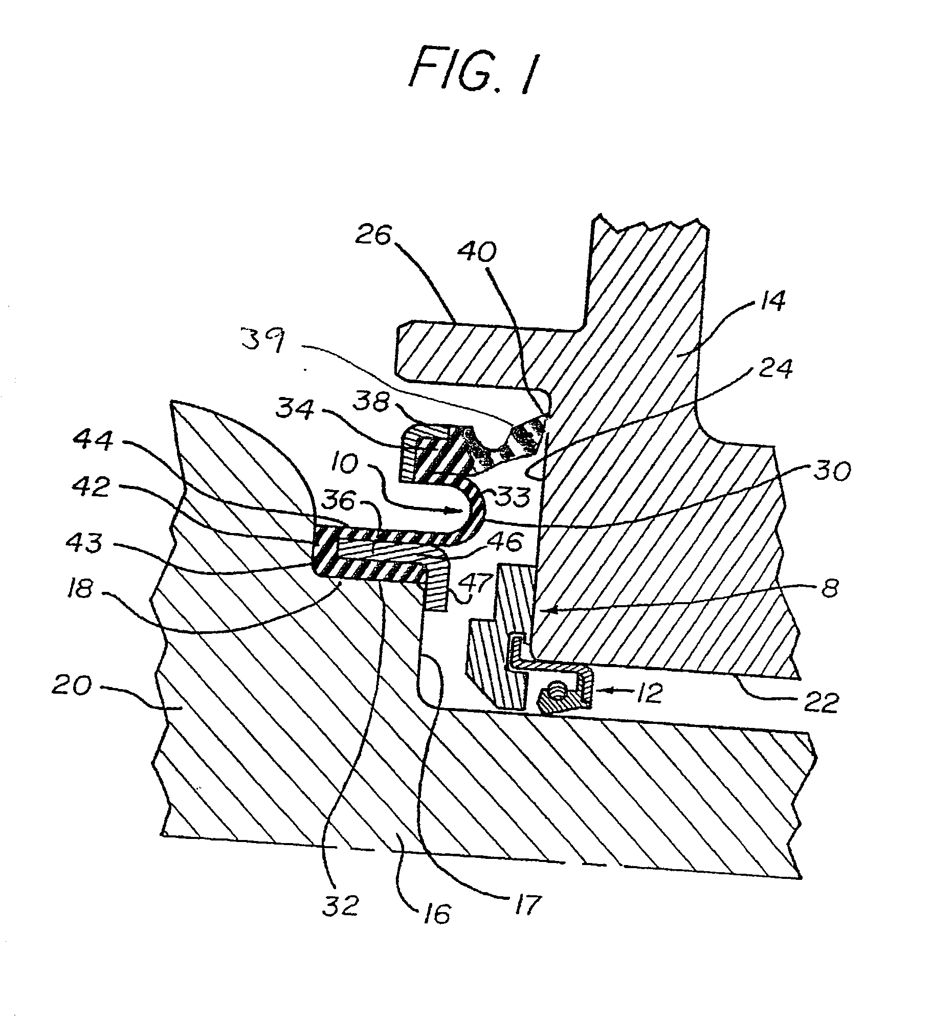
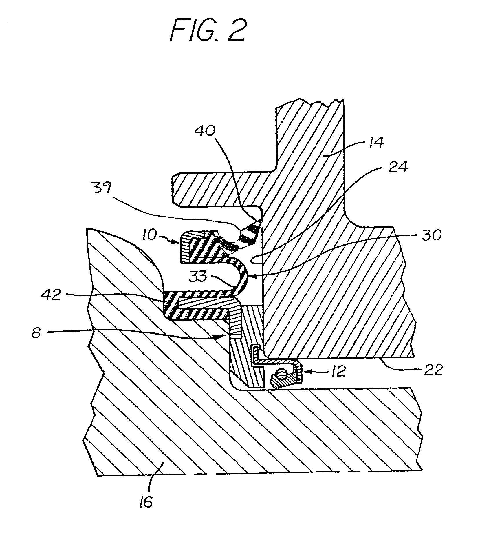
[0058] As illustrated in detail in FIGS. 8 and 9, a preferred form of thrust bearing 12 is of generally annular configuration and is mounted at the inner bore of the spindle housing in sealed relation to the shaft 16 and in journaled relation to the housing 14. The thrust bearing 12 comprises a seal retainer ring 80 having a radially inwardly directed end flange 81 and a radially outwardly directed end flange 82 at the opposite end of the ring 80. An annular seal 83 includes a plastic seal ring 39' (preferably made of PTFE) with a seal lip 84 at its inner radial end and an endless coiled spring member 85 in outer surrounding relation to the seal which acts to compress the seal in an inward radial direction against the surface of the shaft 16. Seal ring 39' is attached to seal element 83 via mechanical and / or chemical bonding.

[0059] A bearing member 86 is composed of a hard, rugged plastic material, such as, an internally lubricated Nylon composition characterized by...


PUM


Abstract

A rotary facial seal and a thrust bearing are adapted to be installed between inner and outer concentric relatively movable members, such as, the spindle housing and axle of a motor vehicle, the facial seal having an annular diaphragm made up of an inner seating portion mounted on the axle, an outer plastic or PTFE sealing ring with a lip tapering away from a hinged section in a seal body to engage a radial wall of the housing, and an intermediate resilient wall section between the seal lip and seating portion to yieldingly urge the sealing lip into a thin band of contact with the radial wall under the biasing action of the intermediate wall section; and the thrust bearing includes a bearing member which is installed at the inner bore of the spindle housing and is freely rotatable with respect to the spindle housing when engaged by the end of the shaft and inner seating portion of the facial seal.

Description

[0001] 1. Field of the Invention[0002] The present invention relates to a seals; and more particularly relates to a novel and improved grease or oil facial seal having a plastic or PTFE used alone or in combination with a bearing assembly disposed between two relatively movable or relatively rotatable parts, such as, a stationary housing and a rotatable and axially movable shaft.[0003] 2. Description of the Related Art[0004] Diaphragm-type seals have been employed in the past in rotary seal applications, such as, between a rotating axle and a spindle housing in a motor vehicle. For example, U.S. Pat. No. 4,502,698 to M. T. Collins, entitled "ROTARY FACE SEAL WITH FLEXIBLE ANNULAR BOOT," discloses a boot mounted in surrounding relation to a shaft or axle and terminating in an outer peripheral seal ring which has a tapered face engaging the radial wall of the outer stationary spindle housing; and a spring member urges the seal ring into firm engagement with the radial wall, the boot b...

Claims


Application Information

Patent Timeline
IPC IPC(8): F16J15/32F16J15/34F16J15/36
CPCF16J15/324F16J15/3456F16J15/36
Inventor CATER, BRIAN B.BOWERS, TODD A.
Owner POLYMER SEALING SOLUTIONS
Why Eureka
Try Eureka