Method and system for determining the degree of polarization of light

a technology of polarization and measurement method, applied in the direction of optical radiation measurement, photoelectric discharge tube, instruments, etc., can solve the problems of measurement uncertainty, measurement technique described above, and insatiable results

Inactive Publication Date: 2003-01-09
AGILENT TECH INC
View PDF0 Cites 29 Cited by
  • Summary
  • Abstract
  • Description
  • Claims
  • Application Information

AI Technical Summary

Problems solved by technology

When the light is partially-elliptically polarized, the measurement technique described above will not yield satisfactory results, because the technique requires the polarized component of the light to be linear.
However, rotation of the po

Method used


Image

  • Method and system for determining the degree of polarization of light
  • Method and system for determining the degree of polarization of light
  • Method and system for determining the degree of polarization of light

Examples


Embodiment Construction

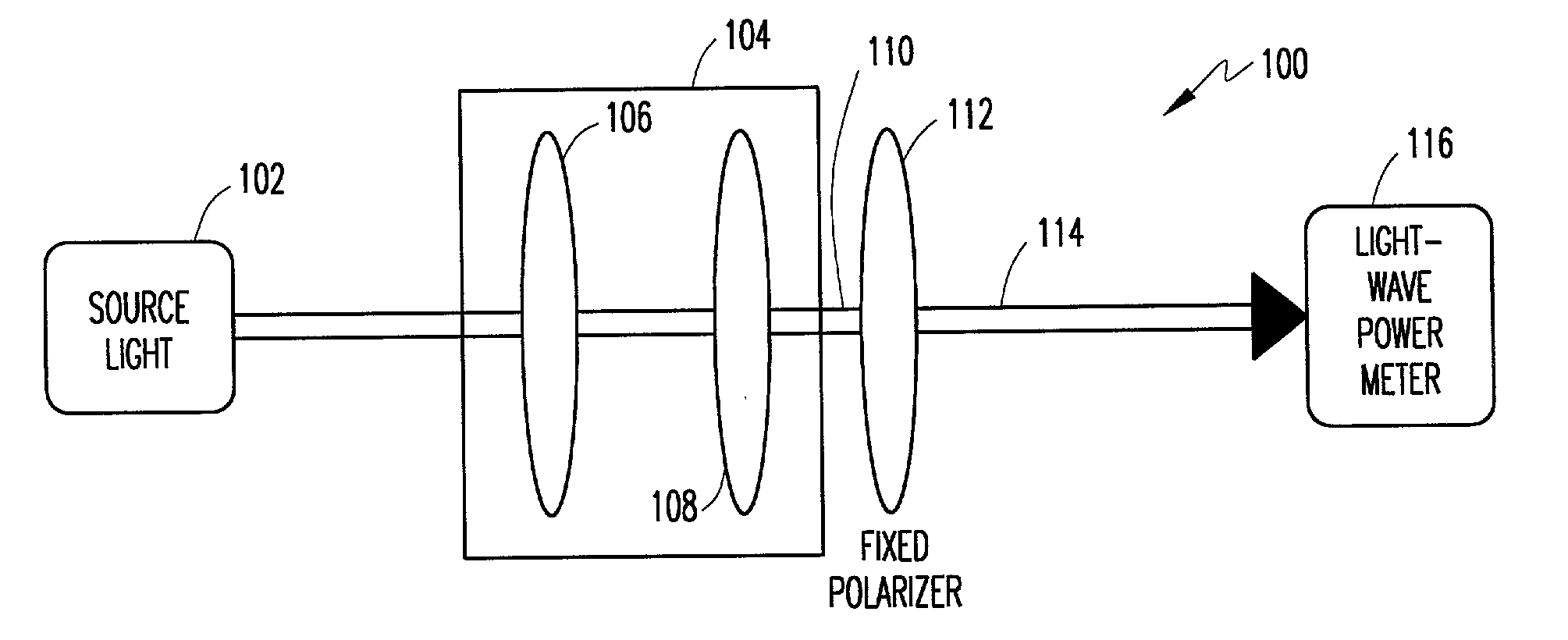
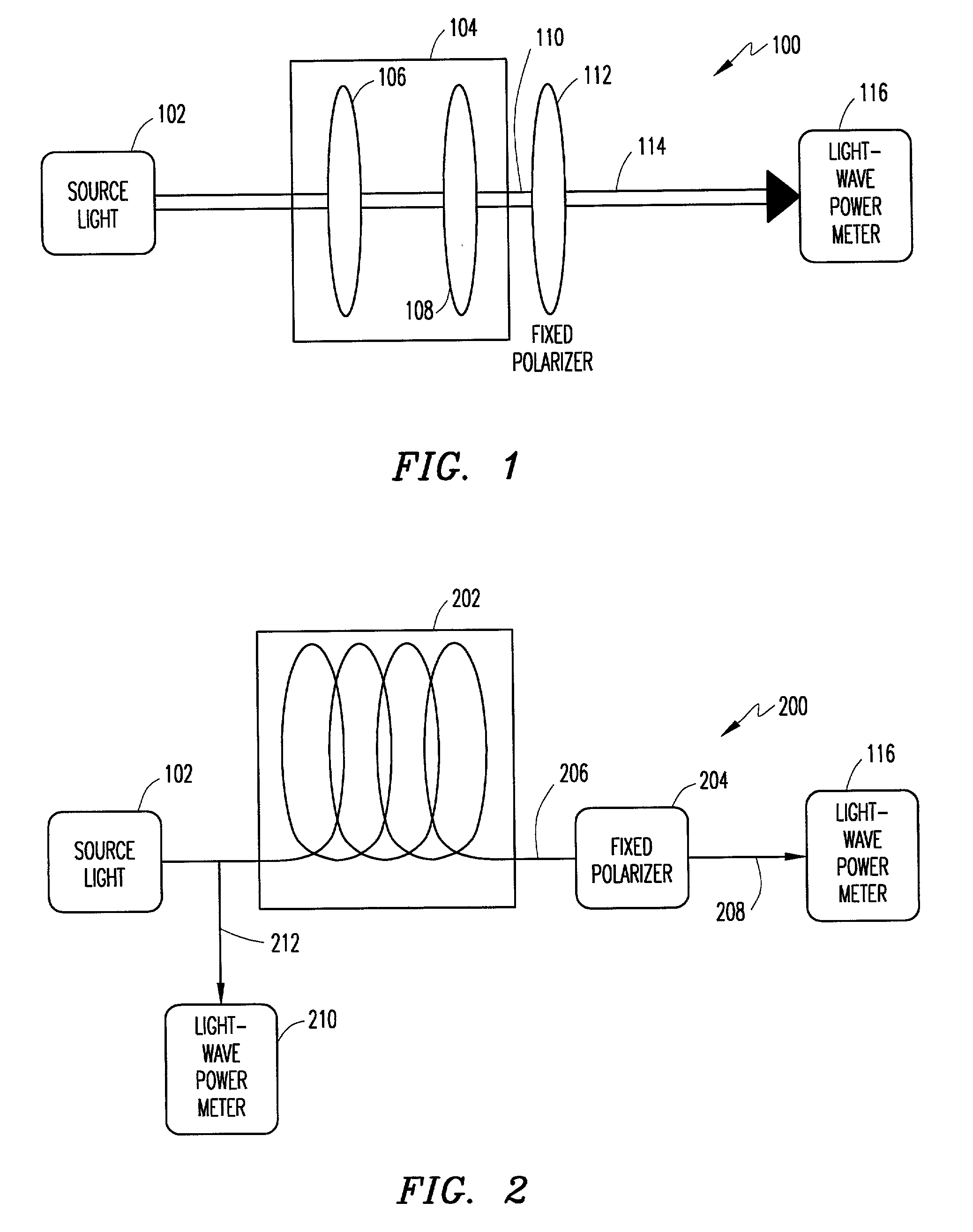
[0033] Any polarization state of linearly-polarized light can be transformed to any other state of linear polarization by transmitting the light through a rotatable half-wave plate Mhwp(a) such that:

S.sub.lpol=M.sub.hwp(.alpha.).multidot.S.sub.in (11)

[0034] A light wave emerging from the half-wave plate (S.sub.lpol) can then be passed through a fixed linear polarizer represented by M.sub.lpol and the transmitted intensity of the light output by the fixed linear polarizer (S.sub.out) measured with a light-wave power meter, such that:

S.sub.out=M.sub.lpol.multidot.S.sub.lpol (12)

S.sub.out=M.sub.lopl.multidot.M.sub.hwp(.alpha.).multidot.S.sub.in (13)

[0035] As the half-wave plate is rotated by .alpha., a minimal and a maximal transmitted intensity of the light output by the fixed linear polarizer can be measured using the light-wave power meter and the DOP determined from the measurements. With this technique for measuring the DOP, the light-wave power meter is subjected to only a single...


PUM


Abstract

Source light of unknown polarization is input into a polarization controller. The polarization controller transforms the polarization of the source light to a plurality of different polarizations. The transformed source light output by the polarization controller is input to a fixed polarizer, which passes a maximal transmitted intensity of the transformed source light at a given transformation perpendicular to an axis of propagation of the source light. The polarizer passes a minimal transmitted intensity of the transformed source light at a transformation orthogonal to the transformation at which the maximal transmitted intensity is passed. The discriminated transformed source light output by the fixed polarizer is input to a light-wave power meter, which measures the intensity thereof. The maximal and minimal measured transmitted intensities of the discriminated transformed source light can be used to determine the DOP of the source light. In the alternative, Mueller calculus can be used to determine the degree of polarization when at least four polarization transformations are performed by the polarization controller and angles by which a half-wave plate and a quarter-wave plate of the polarization controller are rotated are known.

Description

[0001] 1. Technical Field of the Invention[0002] The present invention relates in general to determining the degree of polarization of light having unknown polarization and, more particularly, to determining the degree of polarization by minimizing the effects of polarization dependence of a light-wave power meter.[0003] 2. Description of Related Art[0004] Light is a transverse electromagnetic wave. If light has an electric field vector that resides in a particular fixed plane, the light is said to be polarized in that particular fixed plane. Two orthogonal polarized planar light waves of the same frequency result in a polarized electric field. The light's polarization state is determined by the relative amplitudes and phases of these two light waves.[0005] Unpolarized natural light, such as, for example, sunlight, can be conceptualized as a plurality of randomly-oriented atomic sources, with each source emitting a source of polarized light for only tens of nanoseconds. When electro...

Claims


Application Information

Patent Timeline
IPC IPC(8): G01J4/04
CPCG01J4/04
Inventor ECKERT, JOHN
Owner AGILENT TECH INC
Why Eureka
Try Eureka