Bandwidth extension of acoustic signals

a technology of acoustic signals and bandwidth extension, which is applied in the field of bandwidth extension of acoustic signals, can solve the problems of reducing the transmission capacity of reconstructed voice signals to less than half, and affecting the sound quality of reconstructed voice signals

Inactive Publication Date: 2003-01-09
TELEFON AB LM ERICSSON (PUBL)
View PDF3 Cites 129 Cited by
  • Summary
  • Abstract
  • Description
  • Claims
  • Application Information

AI Technical Summary

Benefits of technology

[0021] According to a preferred embodiment of the invention, the decoder thereby allows a relatively high parameter value to be allocated to a frequency component if the confidence level indicates a comparatively high degree certainty, whereas it allows a relatively low parameter value to be allocated to a frequency component whose confidence level indicates a comparatively low degree certainty.
[0022] In comparison to the previously known solutions, the proposed solution significantly reduces the amount of artefacts being introduced when extending a narrow-band acoustic signal to a wide-band representation. Consequently, a human listener perceives a drastically improved sound quality. This is an especially desired result, since the perceived sound quality is deemed to be a key factor in the success of future telecommunication applications.

Problems solved by technology

Such band-pass filtered acoustic signal is normally perceived by a human listener to have a relatively poor sound quality.
For instance, a reconstructed voice signal is often reported to sound muffled and / or remote from the listener.
However, increasing the bandwidth for each channel by more than a factor two would either reduce the transmission capacity to less than half or imply enormous costs for the network operators in order to expand the transmission resources by a corresponding factor.
Hence, this solution is not attractive from a commercial point-of-view.
Thus, given a particular shape of the narrow-band, there are constraints on the signal properties with respect to the wide-band shape.
However, modelling a wide-band signal from a particular narrow-band signal is still far from trivial.
Unfortunately, the above-described methods all have one undesired characteristic in common, namely that they introduce artefacts in the extended wide-band acoustic signals.
Furthermore, it is not unusual that these artefacts are so annoying and deteriorate the perceived sound quality to such extent that a human listener generally prefers the original narrow-band acoustic signal to the thus extended wide-band acoustic signal.

Method used


Image

  • Bandwidth extension of acoustic signals
  • Bandwidth extension of acoustic signals
  • Bandwidth extension of acoustic signals

Examples


Embodiment Construction

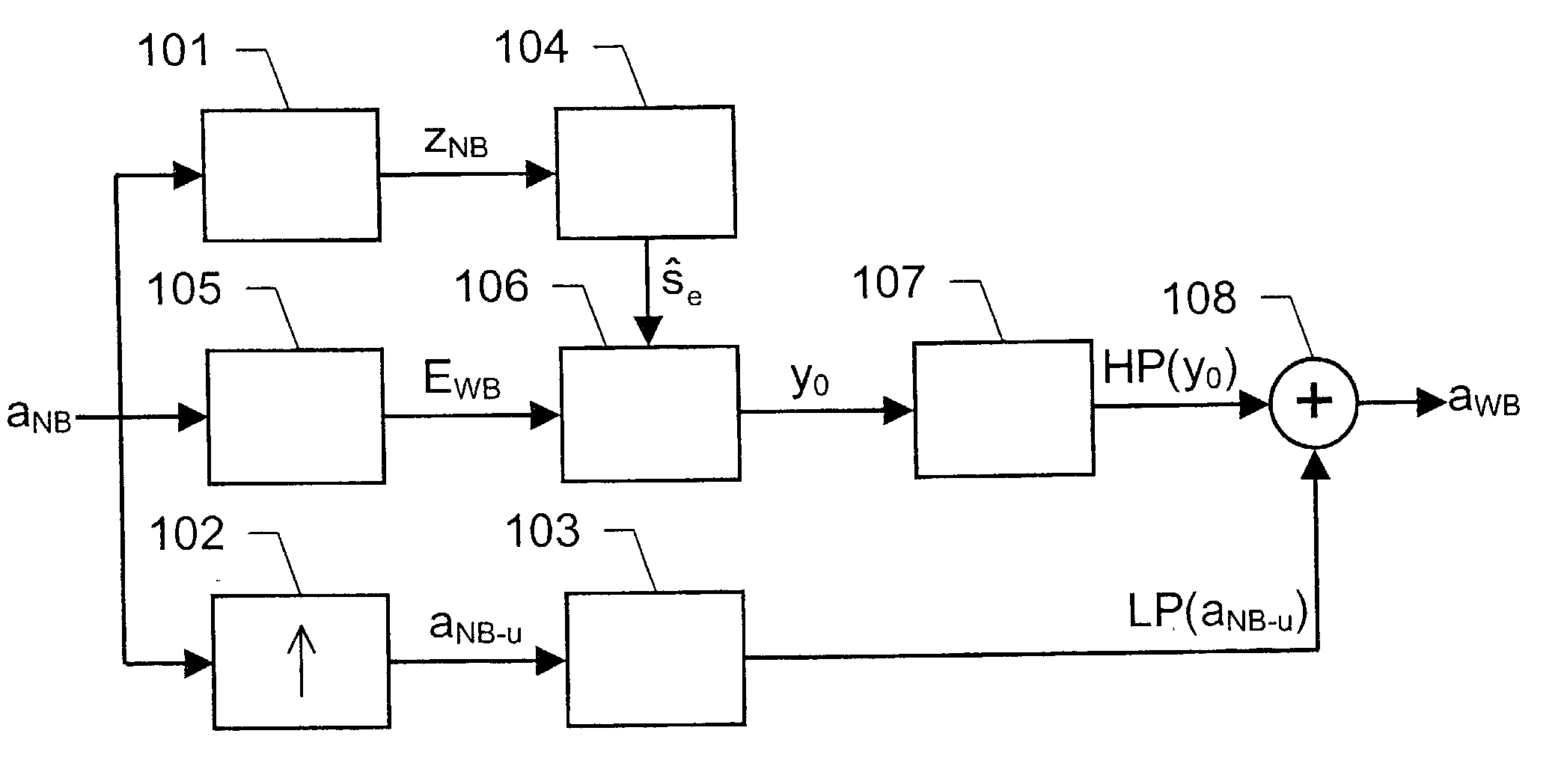
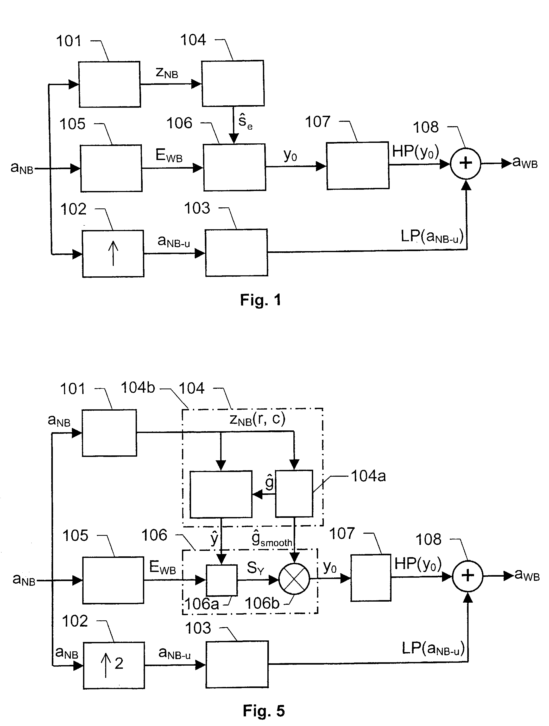
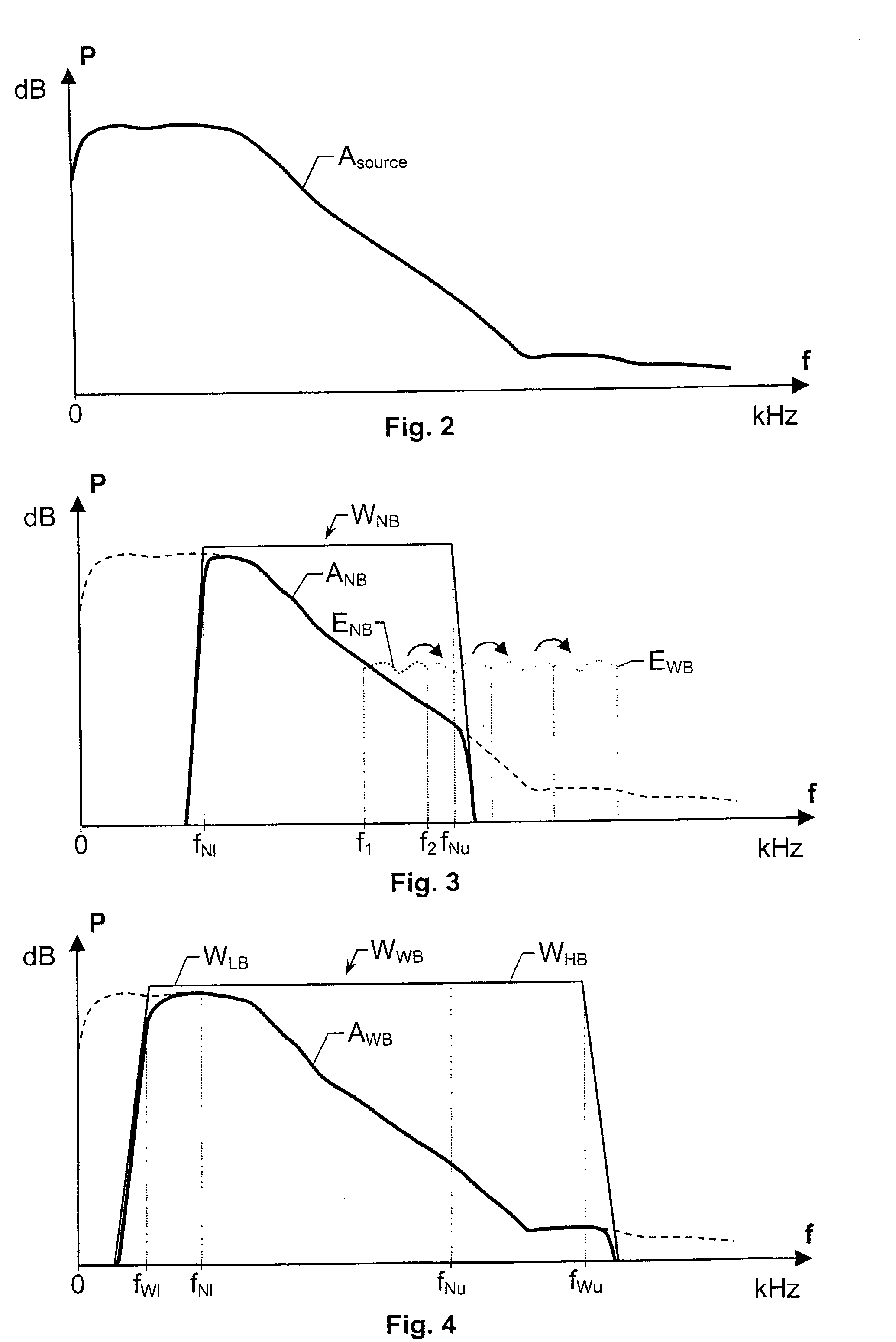
[0033] FIG. 1 shows a block diagram over a general signal decoder according to the invention, which aims at producing a wide-band acoustic signal a.sub.WB on basis of a received narrow-band signal a.sub.NB, such that the wide-band acoustic signal a.sub.WB perceptually resembles an estimated acoustic source signal a.sub.source as much as possible. It is here presumed that the acoustic source signal a.sub.source has a spectrum A.sub.source, which is at least as wide as the bandwidth W.sub.WB of the wide-band acoustic signal a.sub.WB and that the wide-band acoustic signal a.sub.WB has a wider spectrum A.sub.WB than the spectrum A.sub.NB of the narrow-band acoustic signal a.sub.NB, which has been transported via a narrow-band channel that has a bandwidth W.sub.NB. These relationships are illustrated in the FIGS. 2-4. Moreover, the bandwidth W.sub.WB may be sub-divided into a low-band W.sub.LB including frequency components between a low-most bandwidth limit f.sub.WI below a lower bandwi...


PUM


Abstract

The present invention relates to a solution for improving the perceived sound quality of a decoded acoustic signal. The improvement is accomplished by means of extending the spectrum of a received narrow-band acoustic signal (aNB). According to the invention, a wide-band acoustic signal (aWB) is produced by extracting at least one essential attribute (zNB) from the narrow-band acoustic signal (aNB). Parameters, e.g. representing signal energies, with respect to wide-band frequency components outside the spectrum (ANB) of the narrow-band acoustic signal (aNB) are estimated based on the at least one essential attribute (zNB). This estimation involves allocating a parameter value to a wide-band frequency component, based on a corresponding confidence level. For instance, a relatively high parameter value is allowed to be allocated to a frequency component if it has a comparatively high degree certainty. In contrast, a relatively low parameter value is only allowed to be allocated to a frequency component if it is associated with a comparatively low degree certainty.

Description

THE BACKGROUND OF THE INVENTION AND PRIOR ART[0001] The present invention relates generally to the improvement of the perceived sound quality of decoded acoustic signals. More particularly the invention relates to a method of producing a wide-band acoustic signal on basis of a narrow-band acoustic signal according to the preamble of claim 1 and a signal decoder according to the preamble of claim 24. The invention also relates to a computer program according to claim 22 and a computer readable medium according to claim 23.[0002] Today's public switched telephony networks (PSTNs) generally low-pass filter any speech or other acoustic signal that they transport. The low-pass (or, in fact, band-pass) filtering characteristic is caused by the networks' limited channel bandwidth, which typically has a range from 0,3 kHz to 3,4 kHz. Such band-pass filtered acoustic signal is normally perceived by a human listener to have a relatively poor sound quality. For instance, a reconstructed voice ...

Claims


Application Information

Patent Timeline
Patent Type & Authority Applications(United States)
IPC IPC(8): G10L21/038
CPCG10L21/038
Inventor NILSSON, MATTIASKLEIJN, BASTIAAN
Owner TELEFON AB LM ERICSSON (PUBL)
Why Eureka
Try Eureka