
ZTR with steerable wheels

Inactive Publication Date: 2003-01-30
MTD PRODUCTS
View PDF12 Cites 73 Cited by
  • Summary
  • Abstract
  • Description
  • Claims
  • Application Information

AI Technical Summary

Benefits of technology

[0010] It is yet another object of the present invention to provide a ZTR vehicle with a steering system that reduces the drag and wear on ZTR vehicles.

Problems solved by technology

This may cause the portion of the vehicle supported by caster wheels to turn down the hill even when the operator does not wish to turn down the hill.

Method used


Image

  • ZTR with steerable wheels
  • ZTR with steerable wheels
  • ZTR with steerable wheels

Examples


Embodiment Construction

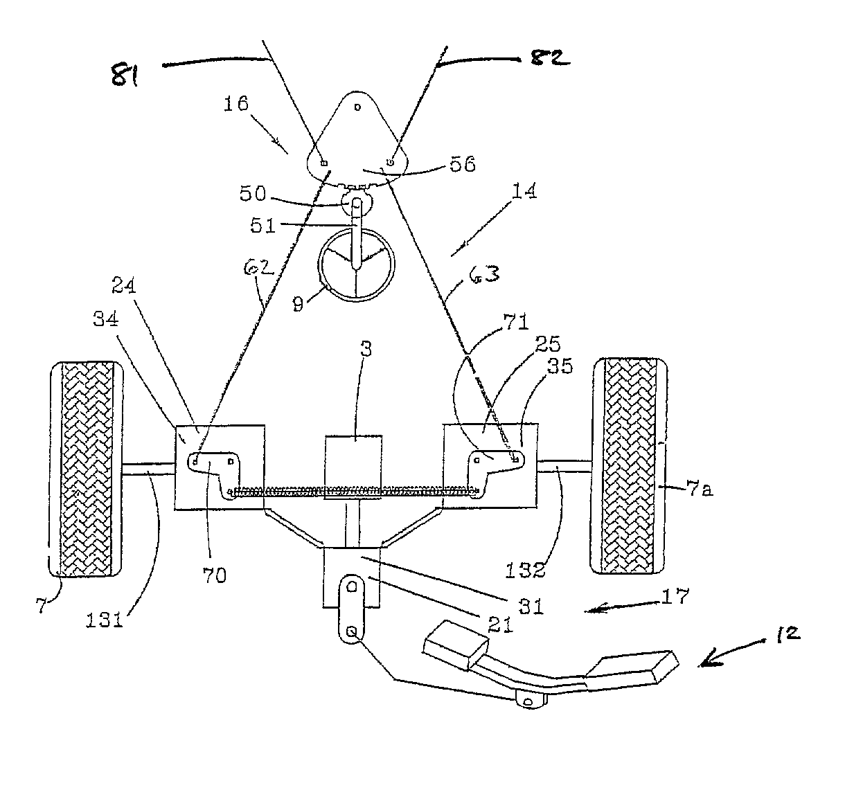
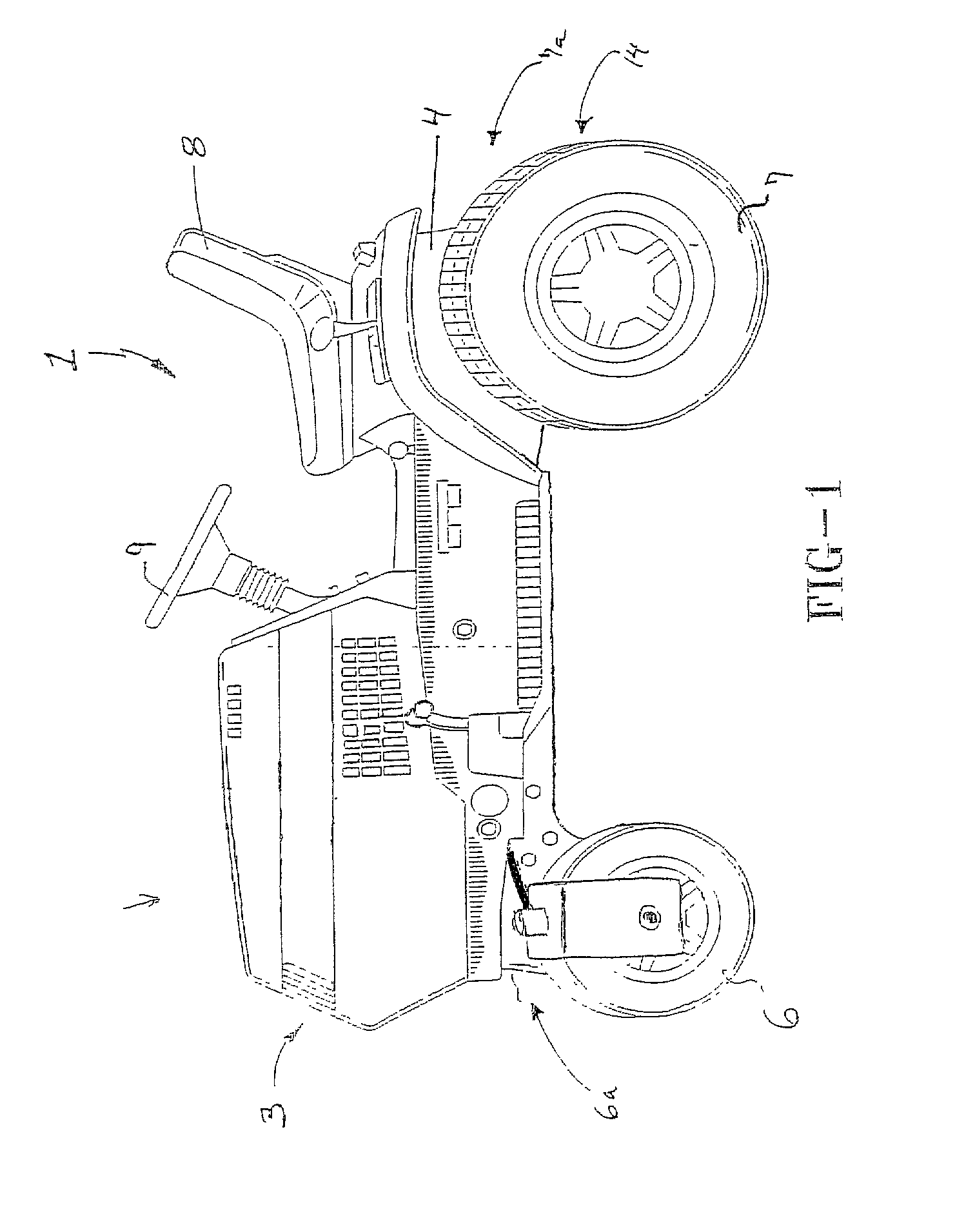
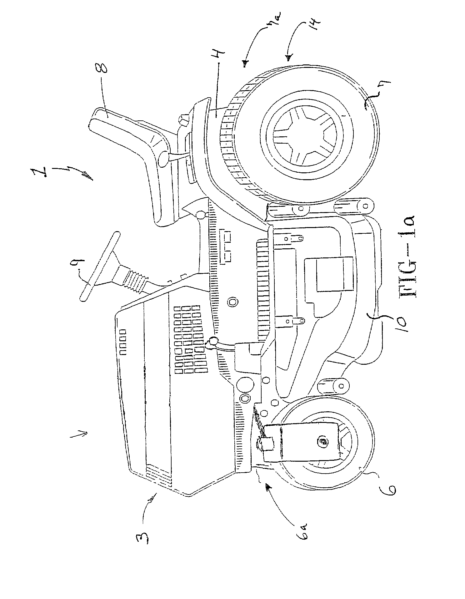
[0028] Referring now to the drawings wherein the showings are for purposes of illustrating a preferred embodiment of the invention only and not for purposes of limiting the same, FIG. 1 depicts a Zero Turning Radius vehicle 1. A Zero Radius Turning vehicle is a vehicle that turns about a point midway between the drive wheels of the vehicle. This may be accomplished by driving the drive wheels in different directions at approximately the same magnitude of speed. In this manner, the radius of turning the vehicle is substantially zero with respect to the lateral midpoint of the vehicle, and more specifically to the midpoint of the drive axle. The radius of turning may be increased from zero to any point interior to the wheelbase of the vehicle 1 or even exterior to the wheelbase of the vehicle as is well know in the art. Any radius of turning may be accomplished by varying the magnitude of the speed and direction of one drive wheel with respect to the other drive wheel. In that turning...


PUM


Abstract

A Zero Turn Radius vehicle is provided that utilizes a steering system including front steerable wheels that is synchronized with a drive system that has dual independent rear drive units to drive the rear wheels as well as steer the vehicle. The synchronization of the steering system with the drive system allows for true zero radius turning and reduced drag and wear on the vehicle especially the ground engaging wheels.

Description

I. BACKGROUND OF THE INVENTION[0001] A. Field of Invention[0002] The present invention relates to the art of vehicles having zero turn radius capabilities, and more specifically to zero turn radius vehicles having steerable wheels.[0003] B. Description of the Related Art[0004] It is known to have a vehicle with zero turn radius capabilities, commonly referred to as a ZTR vehicle. ZTR vehicles are generally propelled by independent drive wheels, which can be driven at different speeds. Steering of the ZTR vehicles is accomplished by driving independent drive wheels each at different rates of speed with respect to the other. Since the independent drive wheels provide steering capabilities for the vehicle, it is generally not necessary to have additional alternate steerable wheels. Therefore, caster wheels are used as the remaining ground engaging wheels for the vehicle in that they can be rotated at any angle as the vehicle is being propelled by the drive wheels. Such vehicles work we...

Claims


Application Information

Patent Timeline
IPC IPC(8): A01D34/69B62D9/00B62D11/24
CPCA01D34/69A01D2101/00B62D9/00B62D11/24
Inventor SCHAEDLER, AXELRUSH, ROBERT
Owner MTD PRODUCTS
Learn More