
Sound reproduction device

Inactive Publication Date: 2003-01-30
PANASONIC CORP
View PDF17 Cites 31 Cited by
  • Summary
  • Abstract
  • Description
  • Claims
  • Application Information

AI Technical Summary

Benefits of technology

[0021] Thus, the invention described herein makes possible the advantage of providing a sound reproduction device which can appropriately drive a plurality of loudspeakers positioned close to each other.

Problems solved by technology

This is because a space in the mobile terminal apparatus is very limited.

Method used


Image

  • Sound reproduction device
  • Sound reproduction device
  • Sound reproduction device

Examples


Embodiment Construction

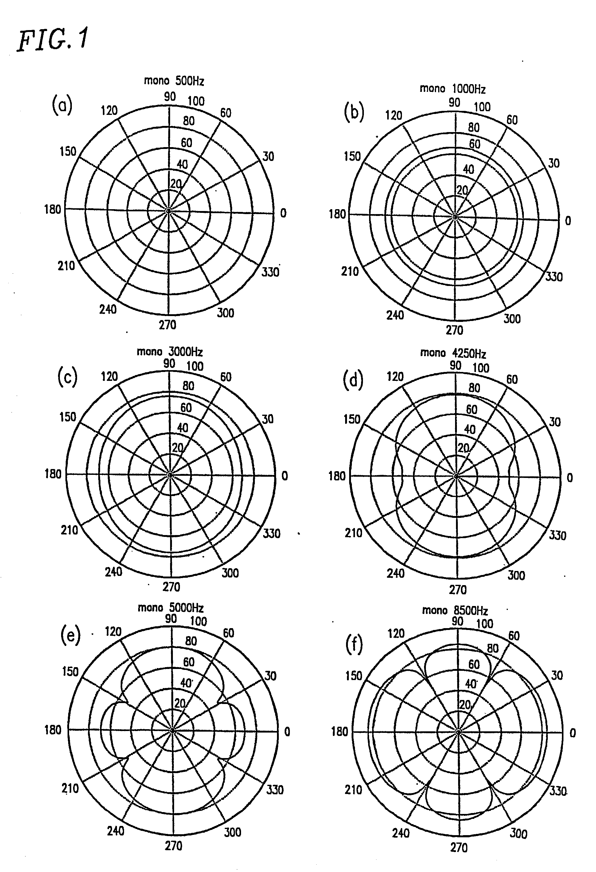
[0040] In order to examine methods for driving a plurality of loudspeakers positioned close to each other, the present inventors conducted experiments with respect to two driving methods (i.e., a method for same-phase driving two loudspeakers and a method for inverse-phase driving two loudspeakers).

[0041] FIG. 1 shows directional characteristics of two loudspeakers measured in experiments in the case where the two loudspeakers are same-phase driven (i.e., driven with signals having the same phase). Here, the experimental conditions are as follows: distance between two loudspeakers: four centimeters (cm); input signals to the two loudspeakers: two signals obtained by distributing a monaural sound signal in equal proportions; and target of measurement: relative sound pressure on a circle having a radius of 50 cm and the center which is the midpoint of a line extending between the two loudspeakers.

[0042] In FIG. 1, each experimental result is indicated by a solid line on a circular cha...


PUM


Abstract

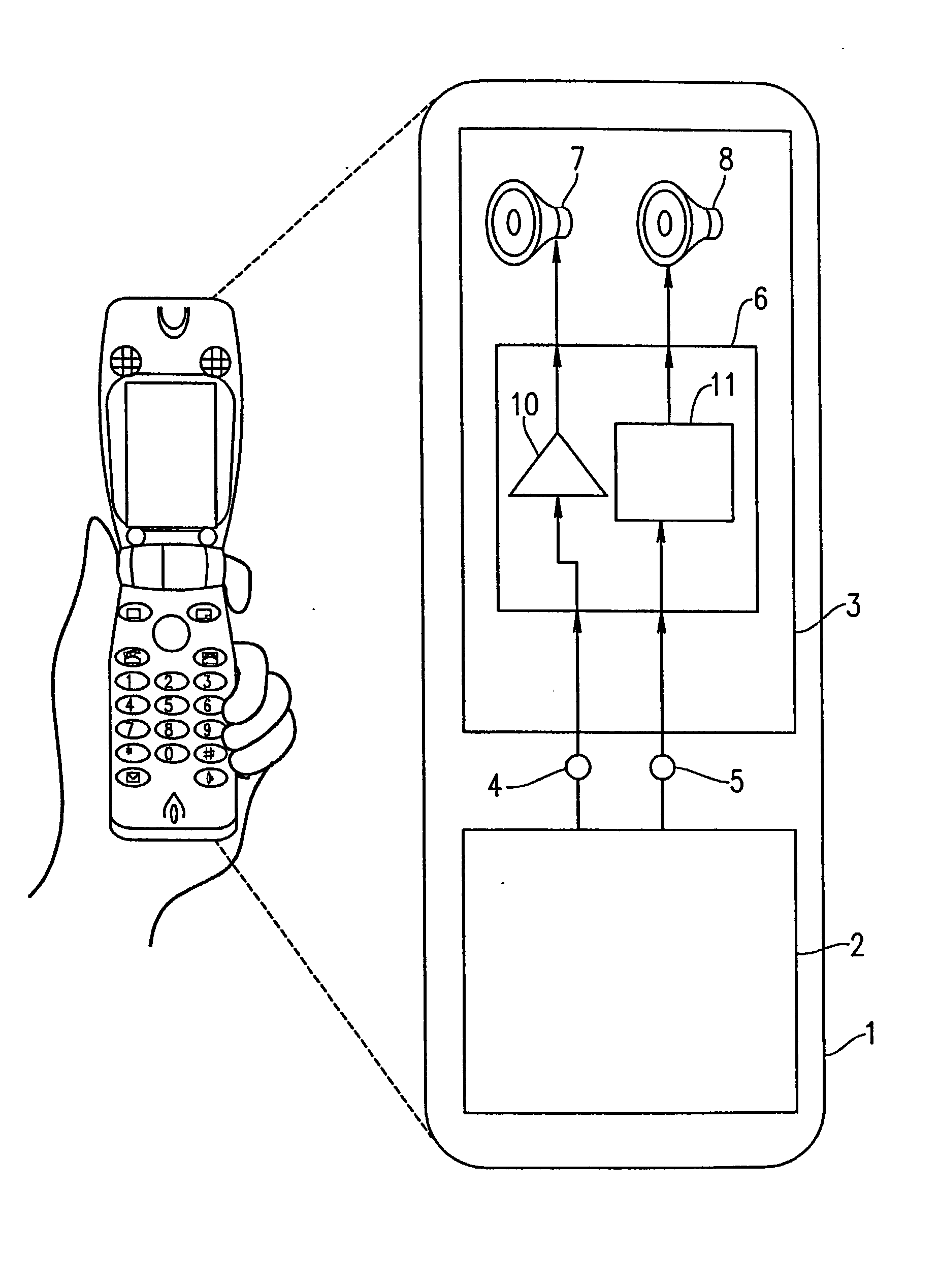
A sound reproduction device of the present invention includes: a first loudspeaker; a second loudspeaker; a first loudspeaker drive section for driving the first and second loudspeakers, the first loudspeaker drive section drives the first and second loudspeakers at substantially the same phase in a first frequency band, and the first loudspeaker drive section drives the first and second loudspeakers at substantially inverse phase and substantially different amplitude levels in a second frequency band higher than the first frequency band.

Description

[0001] 1. Field of the Invention[0002] The present invention relates to a sound reproduction device, and more particularly to a sound reproduction device which can be preferably used in a mobile terminal apparatus.[0003] 2. Description of the Related Art[0004] In recent years, mobile terminal apparatuses, such as cellular phones, Personal Handy Phone Sets (PHS) and Personal Digital Assistants (PDA), have come to have an internet connection function, and therefore the mobile terminal apparatuses are becoming more multifunctional. For example, a mobile terminal apparatus having a function of downloading music data from a music distribution server via the internet so as to store the downloaded music data to a semiconductor memory in the mobile terminal apparatus and a function of reproducing the music data stored in the semiconductor memory is produced on a commercial basis.[0005] In the case where music or a ringtone is represented as a two-channel signal, it is desirable that the num...

Claims


Application Information

Patent Timeline
IPC IPC(8): H04R1/40H04R3/12
CPCH04R1/403H04R3/12
Inventor ABE, KAZUTAKATERAI, KENICHI
Owner PANASONIC CORP
Learn More