Image reading apparatus
a technology of image reading and reading apparatus, applied in the direction of electrical equipment, picture communication, etc., can solve the problems of paper jams, paper jams, and easy transportation failures,
- Summary
- Abstract
- Description
- Claims
- Application Information
AI Technical Summary
Benefits of technology
Problems solved by technology
Method used
Image
Examples
first embodiment
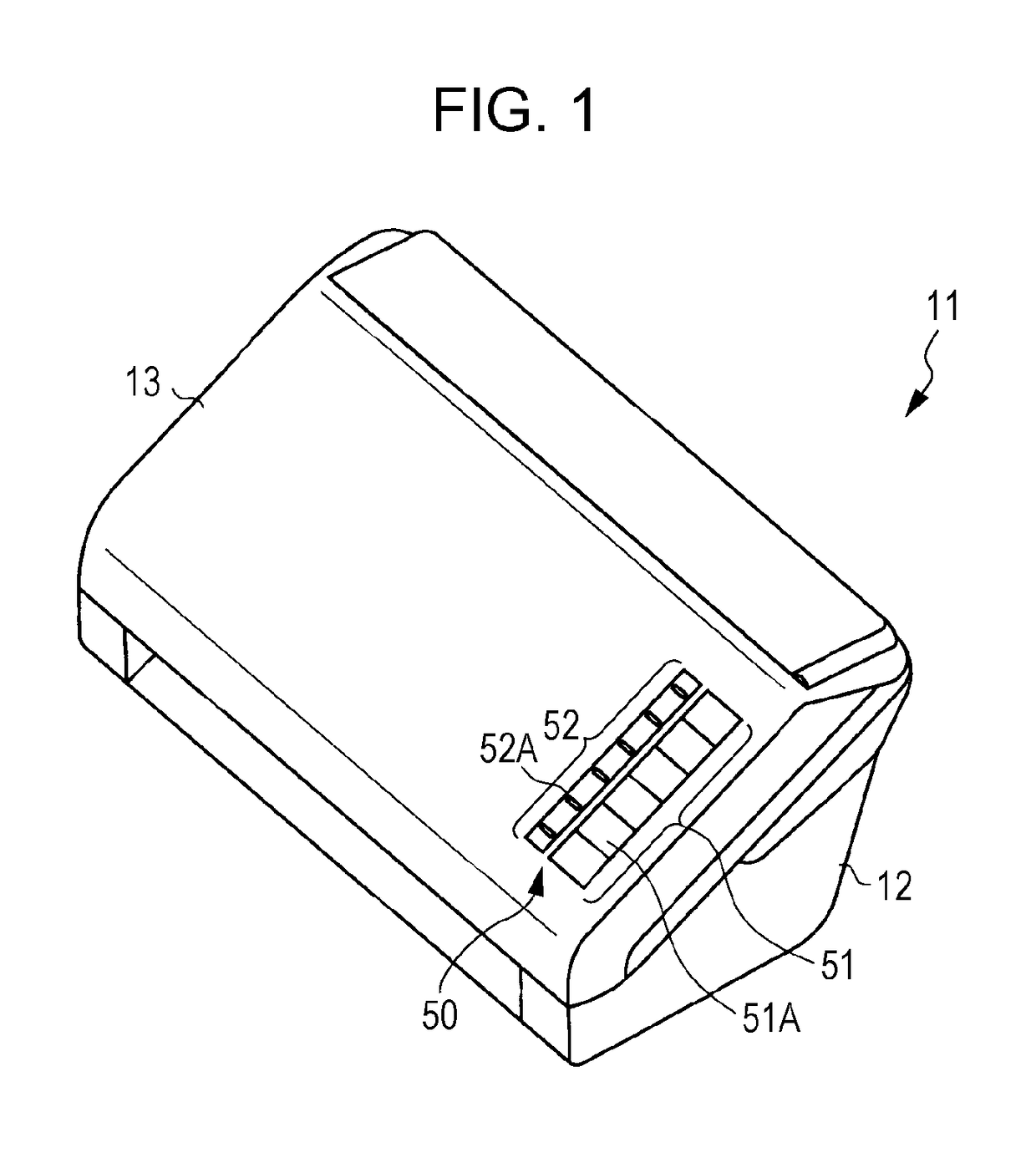
[0041]Hereinafter, a first embodiment in which an image reading apparatus is embodied will be described according to FIGS. 1 to 5.
[0042]As illustrated in FIG. 1, an image reading apparatus 11 according to the embodiment includes a housing 12, and a cover member 13 which is rotatably supported by the housing 12. A user interface 50 of the apparatus is provided in the cover member 13. That is, the user interface 50 includes a plurality of buttons 51, and a plurality of lamps 52.
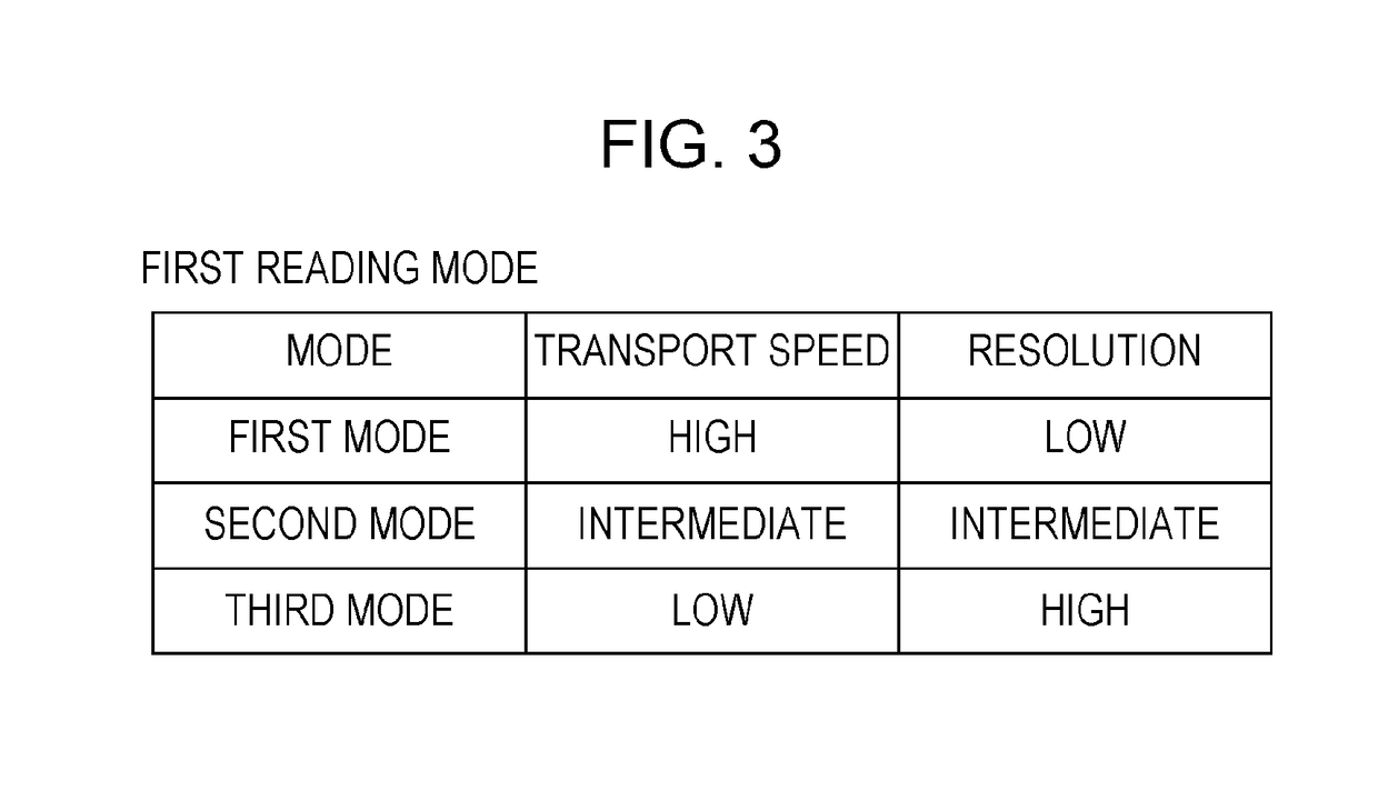
[0043]One button of each of the buttons 51 is a specifying button 51A which is operated when instructing an execution of reading of an image in the second reading mode which will be described later. In addition, one lamp of each of the lamps 52 is a specifying lamp 52A which is turned on when the specifying button 51A enters the ON-state. In addition, the specifying lamp 52A is turned off when the specifying button 51A enters the OFF-state.
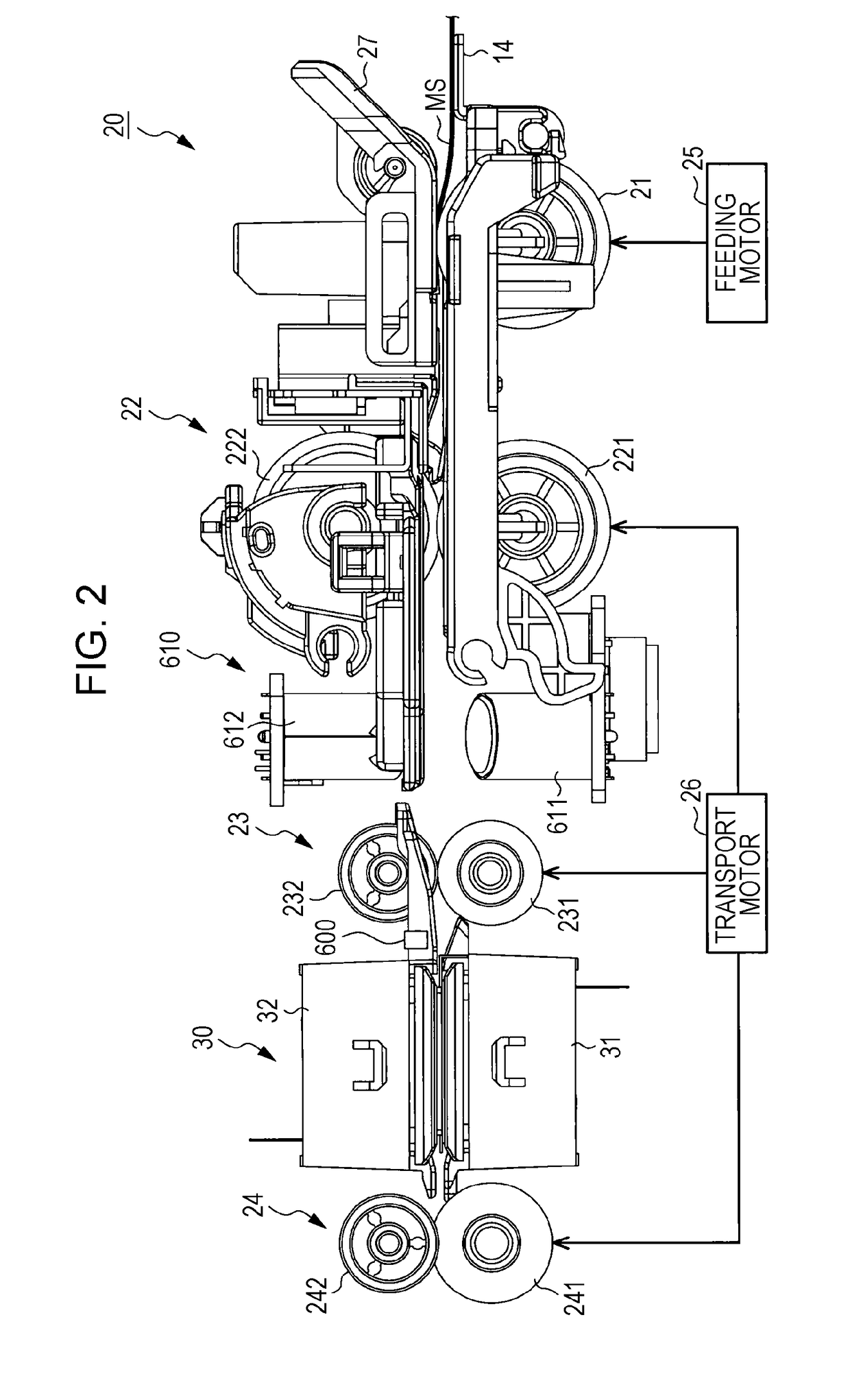
[0044]In addition, as illustrated in FIG. 2, a setting unit 14 in which ...
second embodiment
[0096]Subsequently, a second embodiment in which an image reading apparatus 11 is embodied will be described according to FIG. 6. In addition, in the second embodiment, a part of processing procedure when the specifying button 51A is in the ON-state is different from that in the first embodiment. Accordingly, in the following descriptions, parts which are different from those in the first embodiment will be mainly described, and the same constituent elements as those in the first embodiment are given the same reference numerals, and redundant descriptions will be omitted.
[0097]In FIG. 6, a flowchart for describing a processing procedure when performing reading of an image of a document MS is illustrated.
[0098]As illustrated in FIG. 6, whether or not the specifying button 51A is in the ON-state is determined under a circumstance in which any one mode of the first mode, the second mode, and the third mode is selected (step S11). When the specifying button 51A is in the OFF-state (No i...
third embodiment
[0109]Subsequently, a third embodiment in which an image reading apparatus 11 is embodied will be described with reference to FIGS. 7 and 8. In addition, in the third embodiment, a point of automatically detecting a thickness of a document MS as a reading target of an image, and determining whether to perform the second reading mode or the first reading mode based on the detection result is different from each of the first and second embodiments. Accordingly, in the following descriptions, parts which are different from those in the first and second embodiments will be mainly described, the same constituent elements as those in the first and second embodiment are given the same reference numerals, and redundant descriptions will be omitted.
[0110]A control device 60 of the image reading apparatus 11 will be described with reference to FIG. 7.
[0111]The control device 60 includes a microcomputer which is configured of a CPU, a ROM, and the like, and various driver circuits. As illustra...
PUM
 Abstract
Description
Claims
Application Information
 - R&D
- Intellectual Property
- Life Sciences
- Materials
- Tech Scout
- Unparalleled Data Quality
- Higher Quality Content
- 60% Fewer Hallucinations
Browse by: Latest US Patents, China's latest patents, Technical Efficacy Thesaurus, Application Domain, Technology Topic, Popular Technical Reports.
© 2025 PatSnap. All rights reserved.Legal|Privacy policy|Modern Slavery Act Transparency Statement|Sitemap|About US| Contact US: help@patsnap.com


