Downhole surge reduction method and apparatus

a surge reduction and downhole technology, applied in the direction of fluid removal, sealing/packing, borehole/well accessories, etc., can solve the problems of inconvenient use of tools, ineffective reduction of surge pressure, and inability to effectively circulate mud around the end

Inactive Publication Date: 2003-02-06
ALLAMON INTEREST
View PDF2 Cites 69 Cited by
  • Summary
  • Abstract
  • Description
  • Claims
  • Application Information

AI Technical Summary

Problems solved by technology

While the device of the '881 patent provided for the first time a mechanism for reducing surge pressure, circumstances may be encountered during the running downhole of a drilling / production liner where even a tool in accordance with the '881 patent may be rendered ineffective to reduce surge pressure.
Specifically, if a drilling / production liner encounters a tight hole condition or bridge while being lowered into the wellbore, then it is not possible to effectively circulate mud around the end of the drilling / production liner to help free it.
Once the driller makes this decision, however, he must attempt to lower the drilling / production liner to the target depth without further benefits of surge reduction, since the tool can only be functioned once.
The oil well industry has seen other devices that claim to regulate communication between the wellbore annular space and the well fluid; however, none of these devices provides surge reduction functionality.
In addition, the stated purpose of the '944 device is to regulate the passage and removal of the commodity within the well, not to facilitate surge reduction of a downhole tool.
The opening of the ball valve to permit fluid flow through the packer device and the indexed regions along the wellbore facilitate this purpose and do not provide a means to reduce surge pressure during the running of drilling / production liners.
Furthermore, the stated purpose of the device of the '222 patent is to direct fluid flow into or divert fluid flow from a downhole flow activated tool, and not to implement surge pressure reduction.
In practice, it is believed that substantial problems may be encountered in use of the tool of the '459 patent.
This is because the weight of the drilling / production liner may cause the tool to trip to the open port position, if not locked.
If the rotating drilling / production liner gets caught in the borehole, the continued rotation can result in the running tool becoming disengaged from the drilling / production liner.
This result is undesirable, since the drilling / production liner cannot be properly cemented in place under these conditions.
While the '522 application does provide for a much desired additional sequence of surge reduction functionality, it has been observed that problems may occur during shifting of the tool.
If this happens while the tool is in the open port position, then the tool cannot be shifted out of the surge reduction mode and critical cementing operations cannot be accomplished.

Method used


Image

  • Downhole surge reduction method and apparatus
  • Downhole surge reduction method and apparatus
  • Downhole surge reduction method and apparatus

Examples


Embodiment Construction

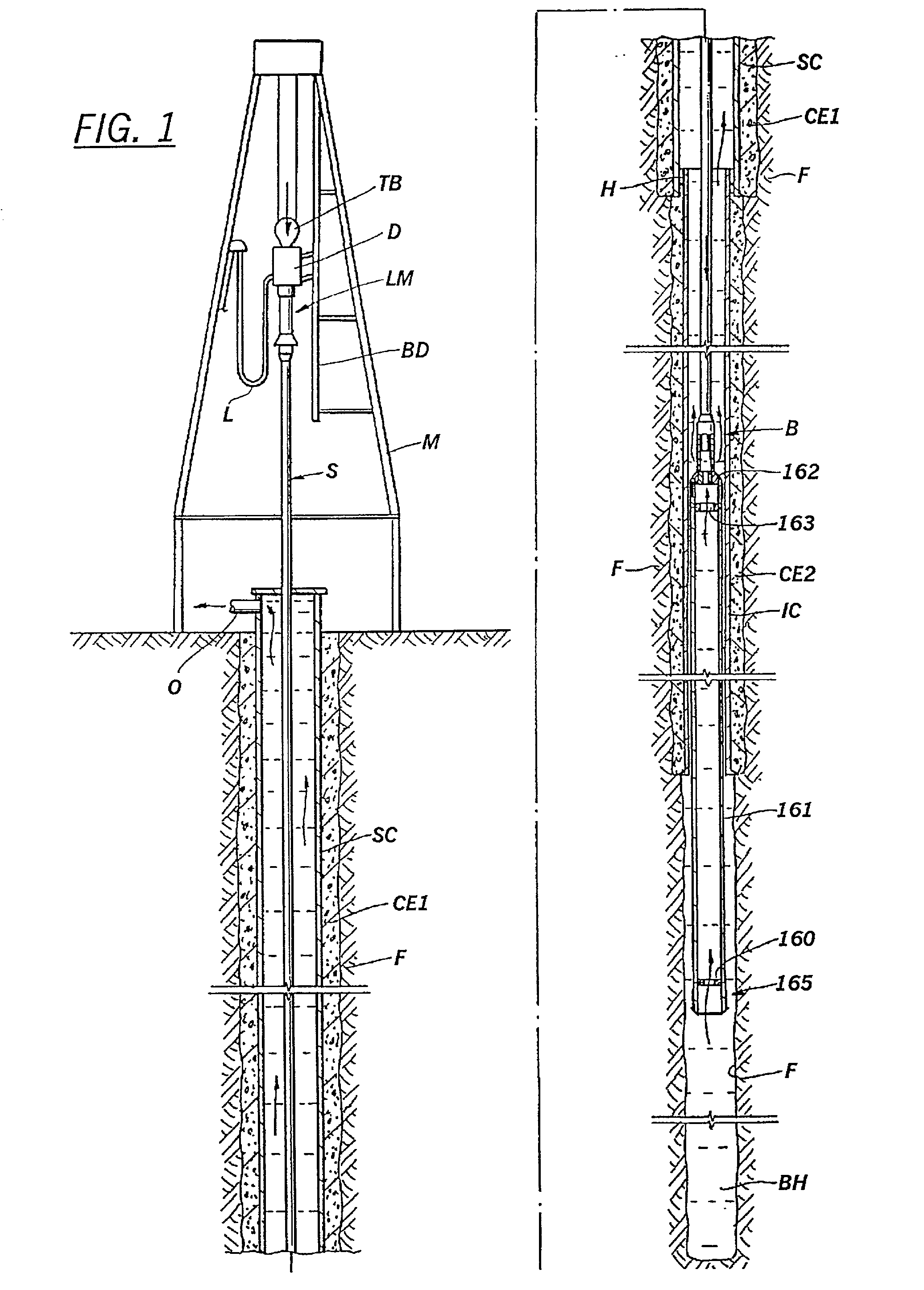
[0045] In oilfield applications, a "drilling / production liner" and a "sub-sea casing" are tubular members which are run on drill pipe. The term "sub-sea casing" is used with respect to offshore drilling operations, while the term "drilling / production liner" is used with respect to both land and offshore drilling operations. For ease of reference in this specification, the present invention is described with respect to a "drilling / production liner." However, it should be appreciated that the present invention may also be used for running a sub-sea casing down a borehole. In the appended claims, the term "tubular member" is intended to embrace either a "drilling / production liner" or a "sub-sea casing." In the specification and appended claims, the term "operatively connected" is used to mean "in direct connection with" or "in connection with via another element," and the term "set" is used to mean "one or more."

[0046] A description of certain embodiments of the present invention is pr...


PUM


Abstract

A method and apparatus for use in the oil well industry for running in drilling/production liners and sub-sea casings down a borehole through drilling fluid on a drill pipe using a multifunction diverter tool with the benefits of surge pressure reduction are disclosed. In accordance with the present invention, a multi-function diverter tool includes a housing assembly with a set of flow holes formed therein and a sliding sleeve arranged within the housing assembly having two sets of flow ports formed therein at different axial locations along the sleeve. By aligning either set of flow ports of the sleeve with the flow holes of the housing, the tool is set in a "surge pressure reduction" mode. By shifting, or axially indexing, the sleeve downward, the set of flow holes becomes blocked by the sleeve thus setting the tool in a "circulation" or "cementing" mode. This shifting or indexing is accomplished using an indexing mechanism. The multi-function diverter tool of the present invention can be shifted from a first "surge pressure reduction" mode to a "circulation mode," from the "circulation mode" to a second "surge pressure reduction" mode, and finally from the second "surge pressure reduction" mode to a "cementing" mode. The indexing mechanism of the present invention includes a return spring and brake system which provides the tool with more reliable shifting functionality.

Description

[0001] The present application is a continuation-in-part of U.S. patent application Ser. No. 09 / 812,522 filed Mar. 20, 2001 which claims the benefit of the filing date of Provisional application Ser. No. 60 / 255,481 filed Dec. 14, 2000.[0002] 1. Field of the Invention[0003] The present invention relates to a method and apparatus for use in the oil well industry, and, more particularly, to a method and apparatus for providing surge reduction functionality while running a drilling / production liner or sub-sea casing downhole.[0004] 2. Description of the Prior Art[0005] The principle of operation of a surge reduction tool is described in U.S. Pat. No. 5,960,881 ("the '881 patent"), which is incorporated herein by reference and which should be referred to with respect to the advantages provided by that invention. In practice, the invention of the '881 patent has provided the oil well industry with the long-desired capability of running in drilling / production liners faster and more reliabl...

Claims


Application Information

Patent Timeline
Patent Type & Authority Applications(United States)
IPC IPC(8): E21B21/10E21B34/10
CPCE21B21/103E21B34/102
Inventor ALLAMON, JERRY P.
Owner ALLAMON INTEREST
Why Eureka
Try Eureka