Suction device provided with negative pressure regulating mechanism

a technology of negative pressure and regulating mechanism, which is applied in the direction of manufacturing tools, transportation and packaging, work holders, etc., can solve the problems of lowering the performance efficiency of such devices, reducing the amount of abrasives which can be suction-transported correspondingly, and it is extremely difficult for brushes to be equipped with a negative pressure adjustment function, such as that of a vacuum breaker

Inactive Publication Date: 2003-02-06
URAKAMI FUKASHI
View PDF6 Cites 8 Cited by
  • Summary
  • Abstract
  • Description
  • Claims
  • Application Information

AI Technical Summary

Problems solved by technology

If the negative pressure inside the pressure-reduced area exceeds a predetermined value, the adhesive power of said device to the surface of an object becomes excessive, causing destruction due to a lack of mechanical strength thereof.
In such a device, if the amount of the fluid decreases, the amount of abrasives which can be suction-transported decreases correspondingly, resulting in lowered performance efficiency of such device.
However, the flow of the fluid which flows from the vacuum breaker and reaches the negative pressure forming means via the interior of the suction housing is not necessarily an effective flow of the fluid to effectively suction-transport powder and granular materials, such as abrasives, existing on the surface; As easily understood in case of such surface of an object being a floor surface, the flow of the fluid which flows from the vacuum breaker and reaches the negative pressure forming means via the interior of the suction housing does not contribute much to the suction-transportation of powder and granular materials, such as abrasives, existing on the surface.
It is extremely difficult, however, to have a brush to be equipped with a negative pressure adjustment function, such as that of a vacuum breaker.
A large vacuum breaker necessarily makes a device larger and causes the manufacturing cost thereof to increase.
If a great quantity of abrasives is sucked in at one time, however, such material becomes blocked up inside the suction hose, resulting in a drastic decrease in the flow of the fluid which flows from outside such suction nozzle, through the interior of the suction nozzle and the suction hose and to the pressure reduction forming means, frequently causing difficulties in the suction and collection of the abrasives.

Method used


Image

  • Suction device provided with negative pressure regulating mechanism
  • Suction device provided with negative pressure regulating mechanism
  • Suction device provided with negative pressure regulating mechanism

Examples


Embodiment Construction

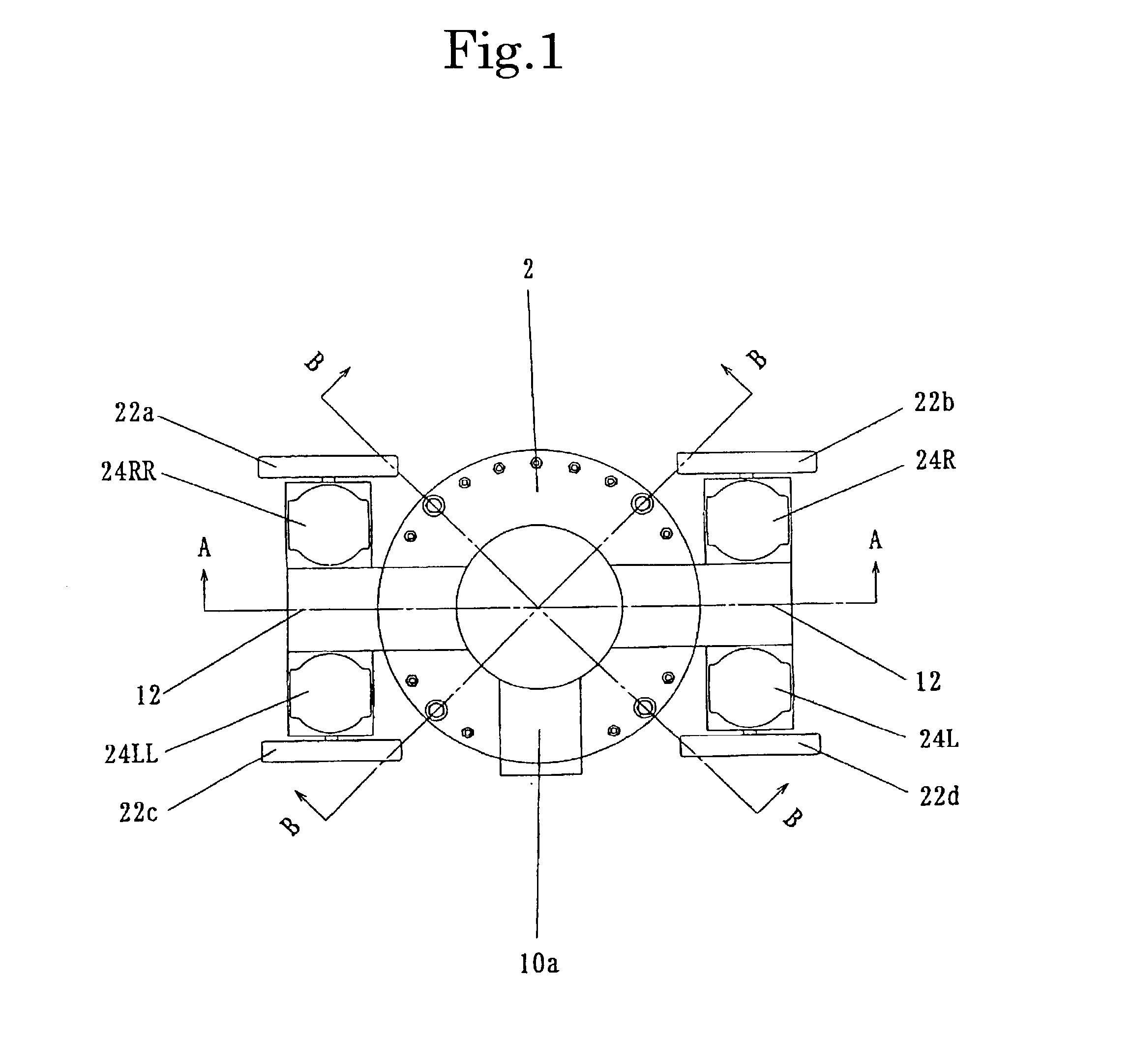
[0043] Preferred embodiments of the device configured according to the present invention will be described in detail below, referring to the figures attached hereto.

[0044] In reference to FIG. 1 through FIG. 12, the device illustrated therein has the suction housing 2, said suction housing 2, made of a rigid material, made up of a cylinder with one end opened and a ring-shaped disk welded onto the outer periphery of such opening of the cylinder.

[0045] Welded onto one side of the suction housing 2 is the connecting pipe 10a, said connecting pipe 10a being connected to a negative pressure forming means (not illustrated), such as a vacuum pump, via flexible suction hose (not illustrated).

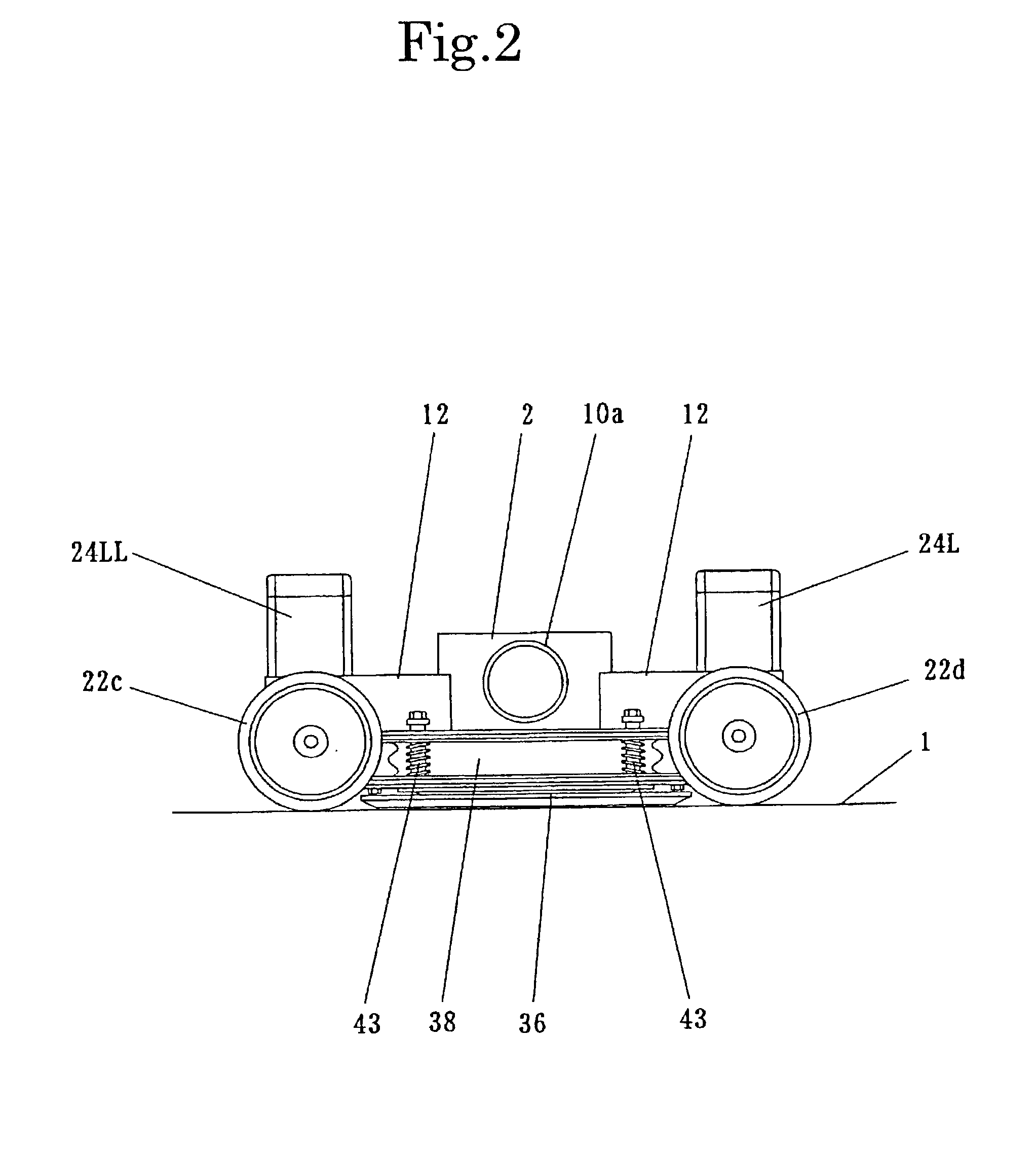
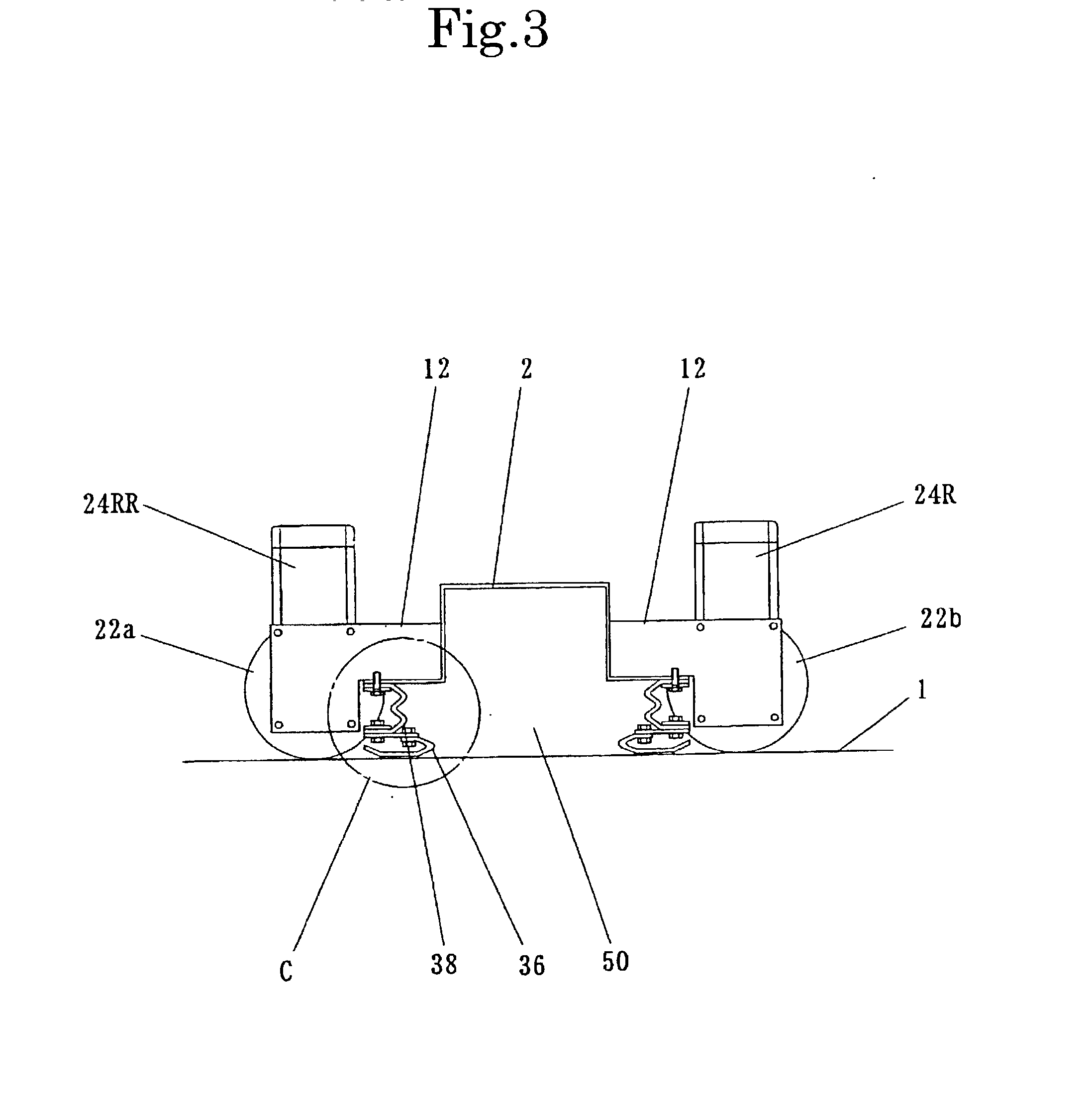
[0046] Welded onto the sides of the suction housing 2 are two sets of installation members for electric motors with reduction gears 12, made of a rigid material.

[0047] Mounted on each of the two sets of installation members for electric motors with reduction gears 12 are the electric motor with a reduc...


PUM


Abstract

The objective of this invention is to provide a device adhering or attempting to adhere to the surface of an object when negative pressure is formed internally, and having a mechanism which adjusts such negative pressure by taking in an ambient fluid such as air or water. Also provided is a device sucking in materials which exist on the surface of an object when negative pressure is formed internally, and having a mechanism which adjusts such negative pressure by taking in an ambient fluid such as air or water. The invention comprises a suction housing connected to a negative pressure forming means to suck in fluids, a suction opening member mounted on the suction housing, a part of which is caused to contact the surface of an object, and which defines a pressure-reduced area together with the suction housing and the surface of an object, and a means for maintaining the distance between the suction housing and the surface of an object at a predetermined distance, wherein the suction opening member and the surface of an object where in contact with each other are caused to be detached from each other partially or entirely due to the increase in the fluid pressure difference between the inside and the outside of the pressure-reduced area, resulting in the communication between the inside and the outside of the pressure-reduced area, allowing the outside fluid to flow into the pressure-reduced area.

Description

[0001] This invention relates to a device adhering or attempting to adhere to the surface of an object when negative pressure is formed internally, and having a mechanism which adjusts such negative pressure by taking in an ambient fluid such as air or water.[0002] The present invention also relates to a device adhering to the surface of an object when negative pressure is formed internally and moving along such surface, and having a mechanism which adjusts such negative pressure by taking in an ambient fluid such as air or water.[0003] The present invention further relates to a device sucking in materials which exist on the surface of an object when negative pressure is formed internally, and having a mechanism which adjusts such negative pressure by taking in an ambient fluid such as air or water.PRIOR ART[0004] An example of those devices that adhere or attempt to adhere to surfaces when negative pressure is formed internally or those devices that adhere to and move along surface...

Claims


Application Information

Patent Timeline
Patent Type & Authority Applications(United States)
IPC IPC(8): B62D57/02B62D57/024
CPCB62D57/02B62D57/024
Inventor URAKAMI, FUKASHI
Owner URAKAMI FUKASHI
Why Eureka
Try Eureka