
Swirl gun

a technology of swirl gun and spherical rod, which is applied in the direction of rigid containers, spraying apparatus, packaging, etc., can solve the problems of poor suited high-pressure applications, poor hoop strength, and difficulty in adjusting the hoop strength, so as to increase the hoop strength

Inactive Publication Date: 2003-04-10
NORDSON CORP
View PDF3 Cites 11 Cited by
  • Summary
  • Abstract
  • Description
  • Claims
  • Application Information

AI Technical Summary

Benefits of technology

[0007] The invention provides a material dispenser having a dispensing tube assembly having an outlet end with an orifice from which material is dispensed onto a surface, and an inlet end having an opening adapted to receive material from a supply during a dispensing operation; and means for imparting orbital motion to said outlet end relative to an axis; the tube assembly having a first section having the inlet end at a first end thereof, a second section having the outlet end at a first end thereof, and a third section that flexibly joins the first and second sections. In one embodiment the flexible third section includes a plurality of rings or hoops to increase hoop strength.
[0009] The use of a flexible yet robust dispensing tube permits a dispenser to be realized that is shorter but capable of providing a wide range of spray pattern dimensions without unduly stressing the moving tube assembly.
[0010] In accordance with another aspect of the invention, a shield liner is used to prevent excessive accumulation of the dispensed material on the gun components. Still a further aspect of the invention provides an air wash feature that uses pressurized air to reduce the amount of dispensed material from coating parts of the gun.

Problems solved by technology

The pivoting option presents problems because the inlet end of the dispensing tube is also a high pressure end at the material inlet.
Although flexible tubes such as plastic can be used, such tubes are not robust and are poorly suited for high pressure applications.
Another problem with known orbiting nozzle guns is that the material being dispensed tends to coat the inside surface of the nozzle shield which is typically a shroud or skirt that surrounds the nozzle.
Longer guns are not only more expensive but also may be more difficult to use or to install into a preexisting spraying system.

Method used


Image

  • Swirl gun
  • Swirl gun
  • Swirl gun

Examples


Embodiment Construction

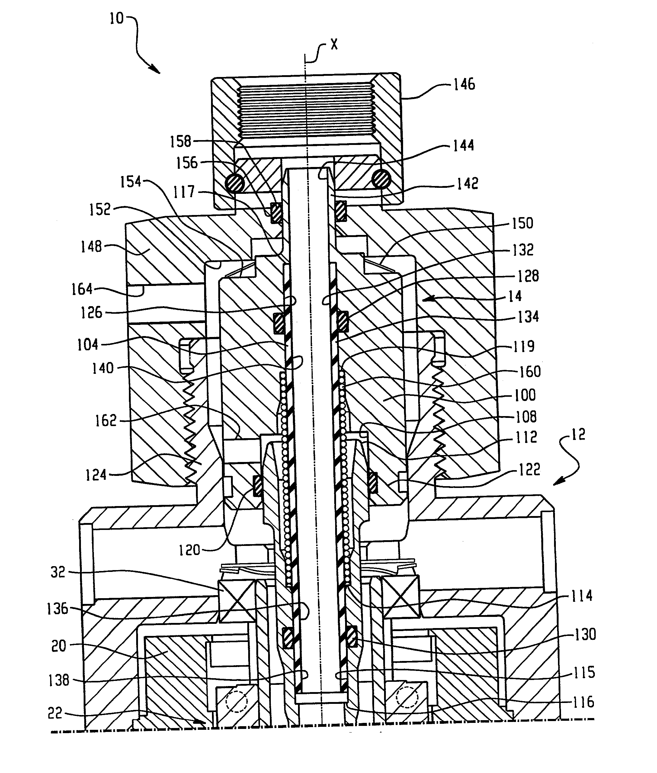
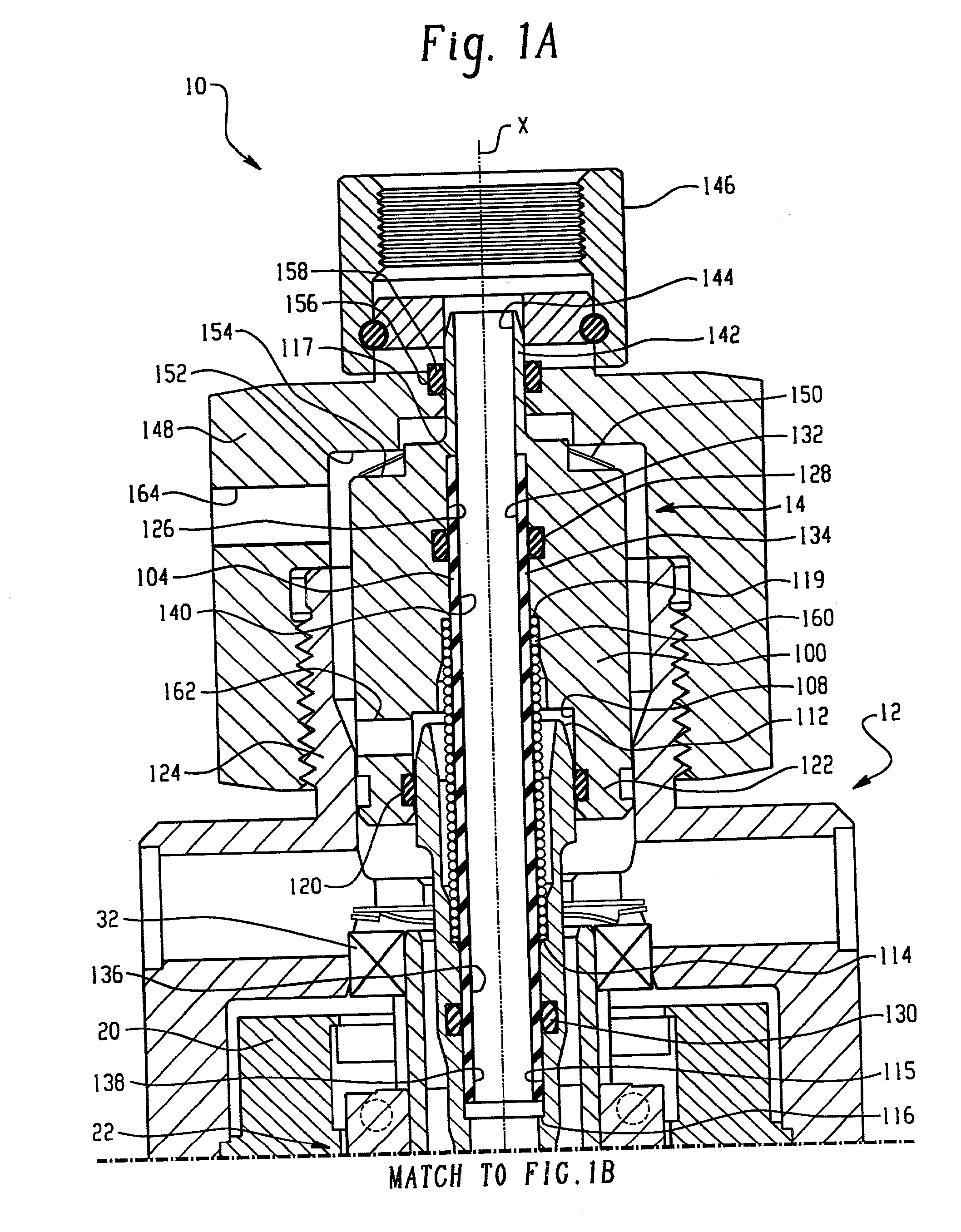
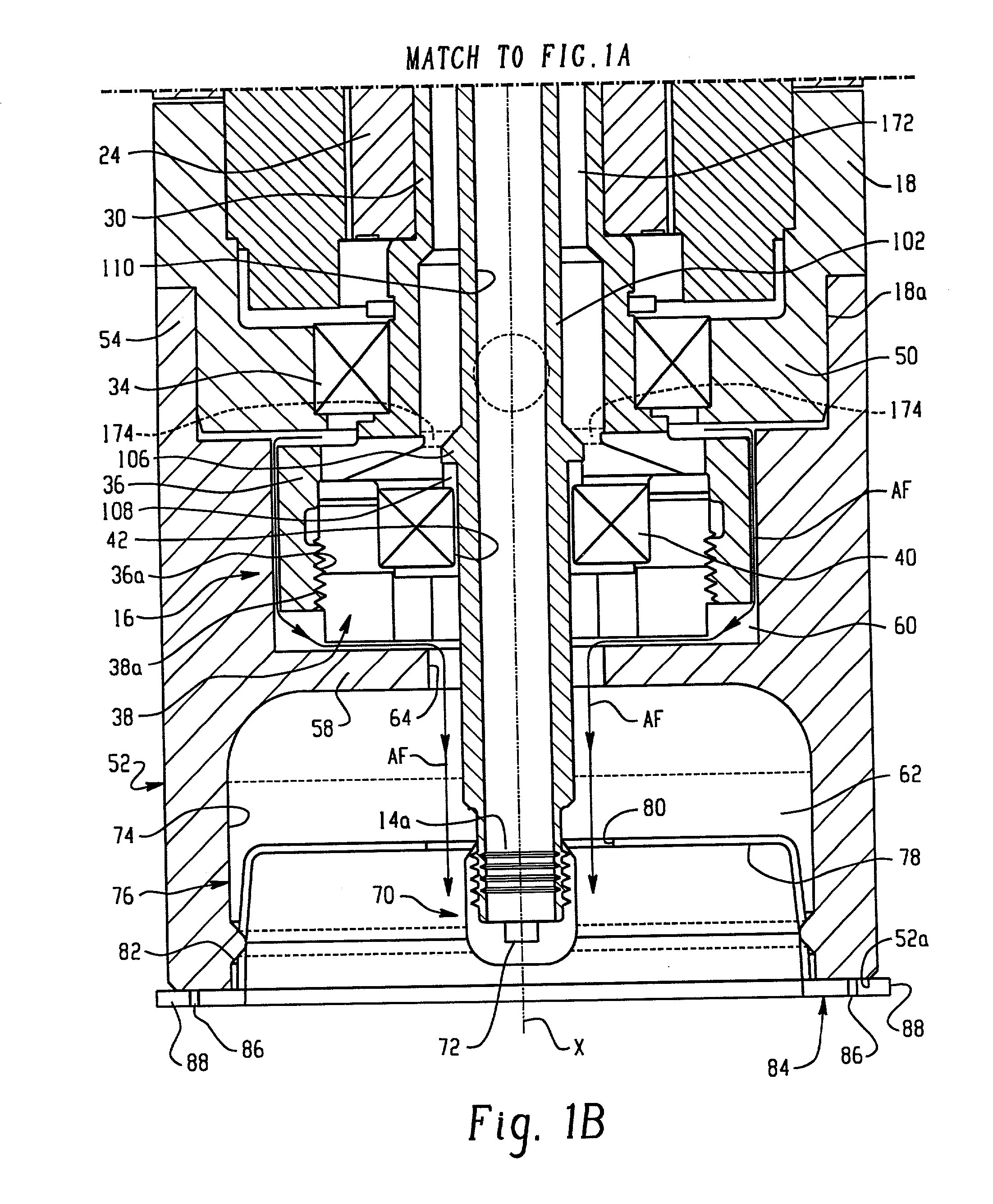
[0018] With reference to FIGS. 1A, 1B and 2A, 2B, an exemplary embodiment of the invention is illustrated in the form of an orbiting nozzle liquid dispensing or applicator apparatus, in this case in the form of a spray gun 10. The illustrated spray gun 10 is well suited for dispensing liquids such as adhesives and sealants, however, the gun 10 may be used for dispensing any liquid onto any suitable surface. Various aspects of the invention are embodied in the gun 10, however, those skilled in the art will appreciate that the various aspects of the invention may be used individually or in various combinations depending on a specific gun design or application requirement.

[0019] The gun 10 includes three basic sections, namely a motor assembly 12, a material dispensing tube assembly 14, and an eccentric or offset bearing assembly 16. Together, the motor assembly 12 and the bearing assembly 16 provide a drive mechanism or means by which an orbiting or nutating motion is imparted to the ...


PUM


Abstract

A material dispenser having a dispensing tube assembly having an outlet end with an orifice from which material is dispensed onto a surface, and an inlet end having an opening adapted to receive material from a supply during a dispensing operation; and means for imparting orbital motion to said outlet end relative to an axis; the tube assembly having a first section having the inlet end at a first end thereof, a second section having the outlet end at a first end thereof, and a third section that flexibly joins the first and second sections. In one embodiment the flexible third section includes a plurality of rings or hoops to increase hoop strength. A shield liner and air wash features are used to reduce the amount of dispensed material that collects on and in the gun. The dispensing tube is arranged to prevent pivoting movement at a primary pressure seal.

Description

[0001] This invention relates generally to fluid dispensing apparatus of the type having an orbiting spray nozzle. More particularly; the invention relates to an orbital dispensing apparatus having a robust yet flexible dispensing tube assembly.[0002] Liquid dispensing apparatus have been designed in a variety of spray gun configurations depending on the type of material being dispensed as well as the configuration of the object or surface being sprayed. One type of dispensing apparatus is an orbiting nozzle type spray gun in which a material dispensing tube is supported for movement at a material inlet end and carries a spray nozzle at a dispensing or outlet end. The dispensing tube extends through the gun relative to a longitudinal reference axis of the gun. The nozzle end typically is journalled in an eccentric bearing. A motor is used to rotate an outer bearing race so as to impart an orbiting or nutating motion to the nozzle relative to the longitudinal axis.[0003] In known des...

Claims


Application Information

Patent Timeline
Patent Type & Authority Applications(United States)
IPC IPC(8): B05B1/02B05B3/02B05B7/02
CPCB05B3/02
Inventor ROMANIN, MARIOSCHNEIDER, ROBERT D.
Owner NORDSON CORP
Learn More