Pipe Fitting Apparatus and Methods

a technology for pipe fittings and fittings, applied in mechanical devices, sleeve/socket joints, couplings, etc., can solve the problems of cumbersome clamping and sealing devices, cumbersome prior injection application methods, and insufficient strength to handle the harsh environment of some piping installations, so as to increase the hoop strength of the pipe fitting, reduce the hoop stress, and increase the hoop strength

Active Publication Date: 2016-03-31
IPS WELD ON DIV
View PDF4 Cites 13 Cited by
  • Summary
  • Abstract
  • Description
  • Claims
  • Application Information

AI Technical Summary

Benefits of technology

[0024]According to some embodiments of the present invention, a reinforcement band, such as a metallic band, is positioned around the tubular member. The reinforcement band increases the hoop strength of the pipe fitting. In some embodiments, the reinforcement band includes a pair of openings formed therein, each opening associated with a respective one of the pair of adhesive injection ports in the pipe fitting.
[0025]According to some embodiments of the present invention, the pipe fitting tubular member includes glass fiber reinforcement (GFR) material, which can increase the hoop strength of the pipe fitting.
[0026]The use of a reinforcement band or GFR material reduces hoop stress in the wall of the socket of a pipe fitting and improves the dimensional stability of the pipe fitting, particularly in high pressure / temperature applications. As such, the use of GFR material in a pipe fitting and the use of a reinforcement band provides additional flexibility to a piping system designer when selecting a cost effective solution to the pressure requirements of a given piping system.

Problems solved by technology

However, each one of these methods presents challenges varying from VOC emissions to the need for power tools and all heavily rely on skilled labor for the success of the union.
Though bonding agents have been in use for decades, they typically have not been strong enough to handle the harsh environments of some piping installations.
Prior injection application methods may involve cumbersome clamps and sealing devices that are installed prior to injecting a bonding agent.
These cumbersome clamps and sealing devices incorporate some form of secondary additional seal at the socket bottom to prevent leakage of the bonding agent during the injection process.

Method used


Image

  • Pipe Fitting Apparatus and Methods
  • Pipe Fitting Apparatus and Methods
  • Pipe Fitting Apparatus and Methods

Examples


Embodiment Construction

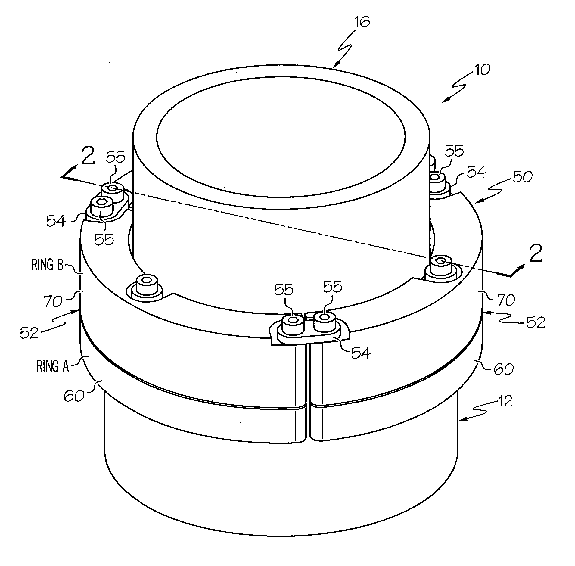
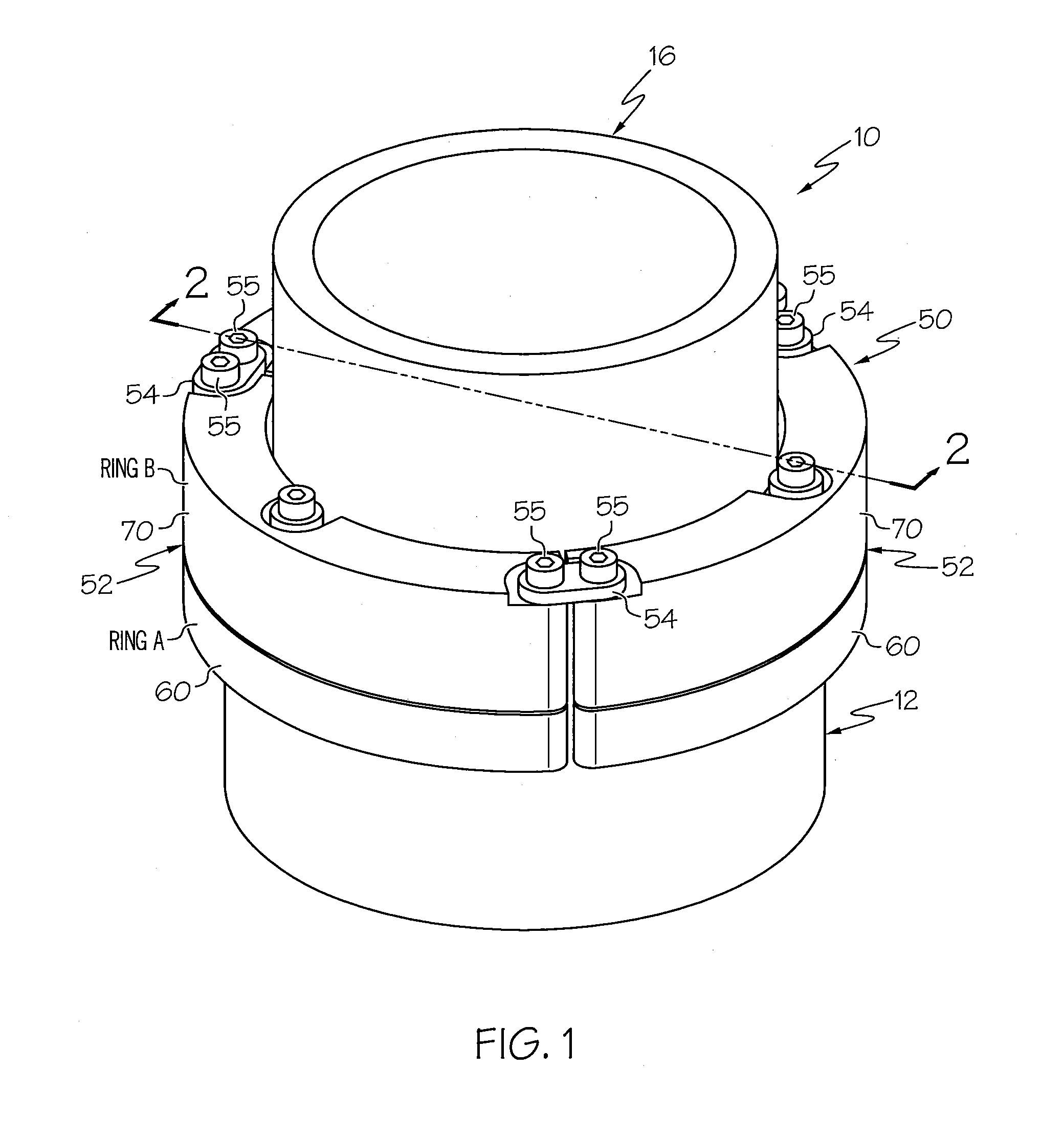
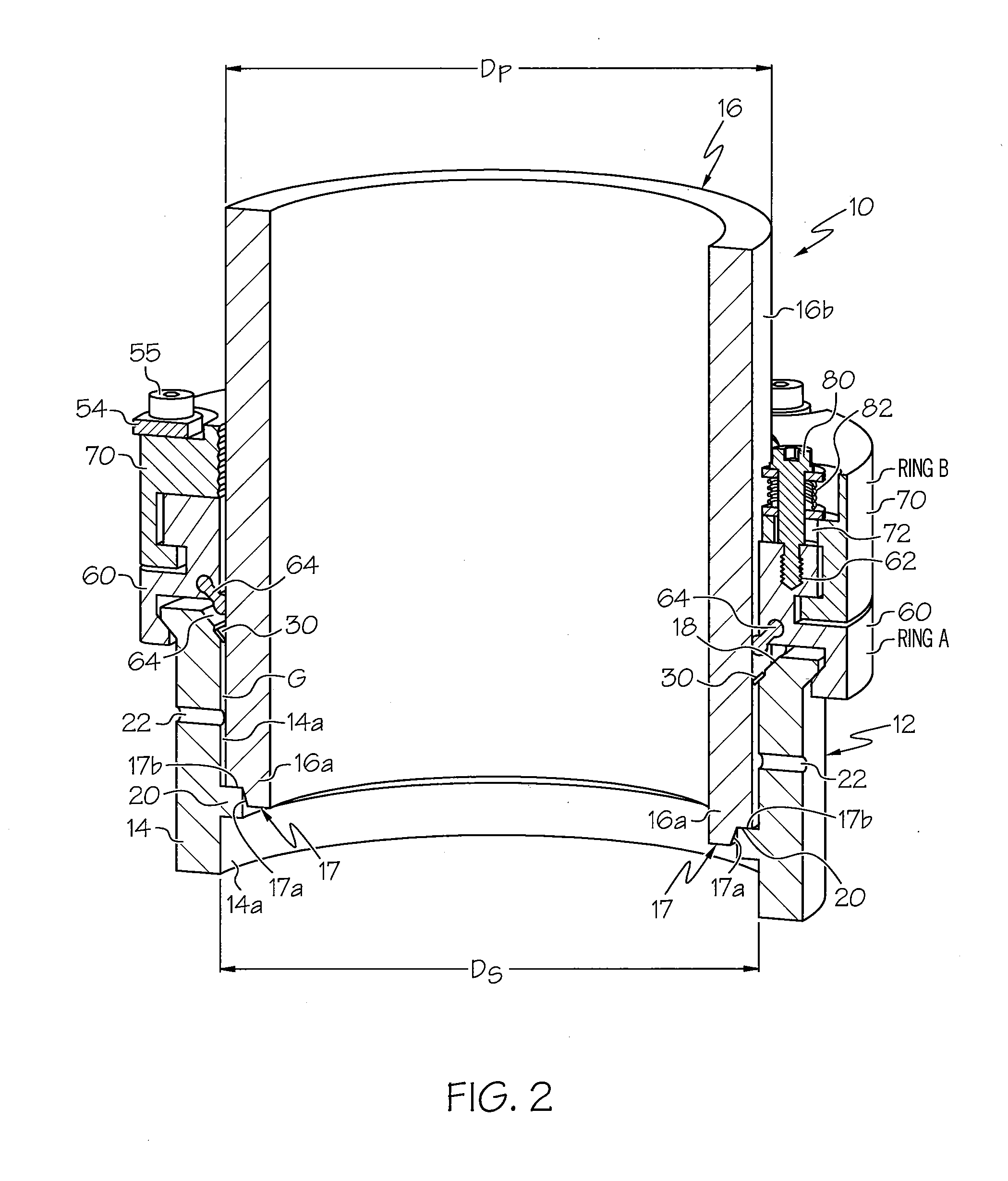
[0049]The present invention will now be described more fully hereinafter with reference to the accompanying figures, in which embodiments of the invention are shown. This invention may, however, be embodied in many different forms and should not be construed as limited to the embodiments set forth herein. Like numbers refer to like elements throughout. In the figures, certain components or features may be exaggerated for clarity, and broken lines may illustrate optional features or elements unless specified otherwise. In addition, the sequence of operations (or steps) is not limited to the order presented in the figures and / or claims unless specifically indicated otherwise. Features described with respect to one figure or embodiment can be associated with another embodiment or figure although not specifically described or shown as such.

[0050]It will be understood that when a feature or element is referred to as being “on” another feature or element, it can be directly on the other f...


PUM

PropertyMeasurementUnit
lengthaaaaaaaaaa
distanceaaaaaaaaaa
lengthaaaaaaaaaa

Abstract

A pipe fitting includes a tubular member comprising a socket and a centering device within the socket. The socket is configured to receive an end of a pipe section therein such that a gap exists between an outer surface of the pipe section and an inner surface of the socket. An annular pipe stop extends from the inner surface of the socket and is configured to matingly engage with the end of the pipe section. A pair of ports extend through the tubular member in circumferentially spaced-apart relationship and are in fluid communication with the gap. The centering device is configured to maintain a coaxial relationship between the pipe section and the socket and such that the gap is substantially circumferentially uniform. A removable and reusable clamp secures the pipe section within the socket as a bonding agent is extruded into the gap via one of the ports.

Description

RELATED APPLICATIONS[0001]This application claims the benefit of and priority to U.S. Provisional Patent Application No. 62 / 056,143, filed Sep. 26, 2014, and U.S. Provisional Patent Application No. 62 / 147,181, filed Apr. 14, 2015, the disclosures of which are incorporated herein by reference as if set forth in their entireties.FIELD OF THE INVENTION[0002]The present invention relates generally to pipes and fittings, more particularly, to joining pipes and fittings.BACKGROUND OF THE INVENTION[0003]The vast majority of connections of piping components (pipe, valves, fittings, etc.) require the connection to be permanent and not something that can be disassembled like a threaded or flanged connection (i.e. mechanical joint). Depending on the piping system materials, permanent jointing methods such as solvent cementing, heat fusion, welding and fiberglass hand layup have been utilized. However, each one of these methods presents challenges varying from VOC emissions to the need for powe...

Claims


Application Information

Patent Timeline
Patent Type & Authority Applications(United States)
IPC IPC(8): F16L37/10F16L13/11F16L21/08
CPCF16L37/10F16L21/08F16L13/116F16L47/02B29C65/542B29C66/5221
Inventor ROACH, JACKCASTELLANI, FABIOBOYE, JORDAN
Owner IPS WELD ON DIV
Why Eureka
Try Eureka