System and method of providing visual documentation during surgery

a visual documentation and surgical technology, applied in the field of stereoscopic surgical microscopic system, can solve the problems of difficult observation, difficult to provide advice, difficult to remove or suture,

Inactive Publication Date: 2003-04-17
3D VISION SYST
View PDF28 Cites 111 Cited by
  • Summary
  • Abstract
  • Description
  • Claims
  • Application Information

AI Technical Summary

Problems solved by technology

During the operation, the ink tends to be washed away because of frequent irrigations necessary to keep the surface of the eye moist, making such excisions or sutures difficult.
Advisors in re

Method used


Image

  • System and method of providing visual documentation during surgery
  • System and method of providing visual documentation during surgery
  • System and method of providing visual documentation during surgery

Examples


Embodiment Construction

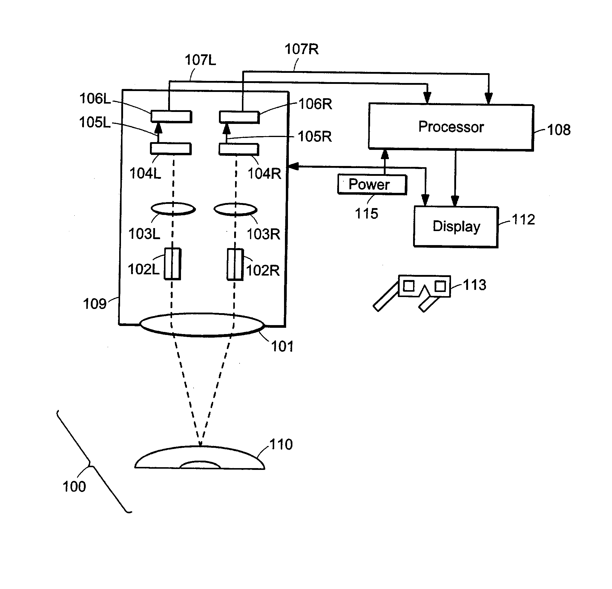
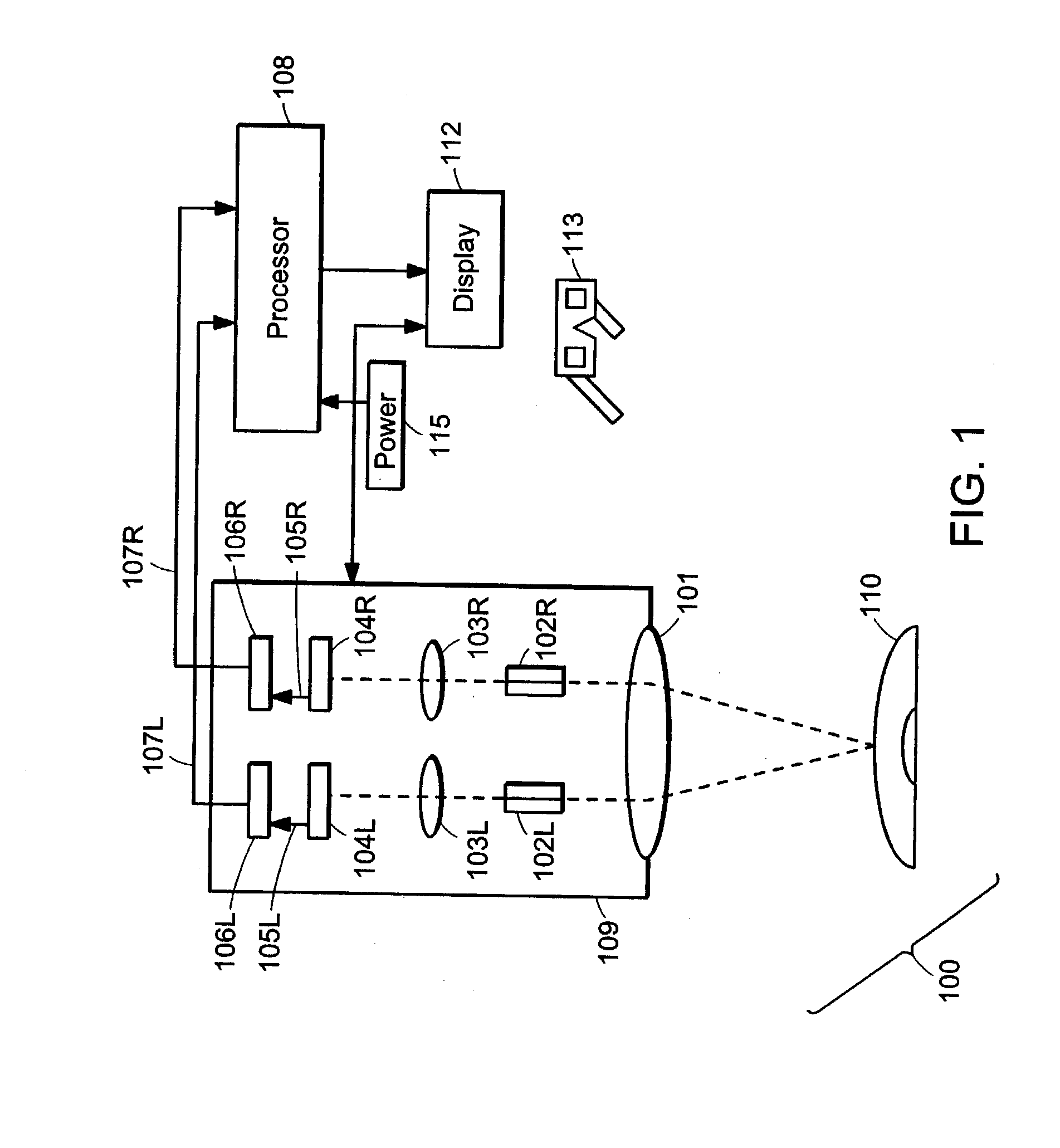
[0017] FIG. 1 is a block diagram of a stereoscopic surgical microscopic system 100, in accordance with one embodiment of the invention. Such a system may be used in, but not limited to, ophthalmic surgery, cerebral surgery, cosmetic surgery, and ear, nose and throat surgery. The system includes at least one stereoscopic video camera 109 for generating a video signal(s) representing a stereoscopic view pair of a surgical subject 110. The video signal is provided to one or more displays 112. An intelligence component, which may include, without limitation, a processor 108, provides a template having a graphical content pertinent to the subject of the stereoscopic view pair. The template is displayed on at least one of the displays 112, and may be advantageously overlaid contemporaneously with the stereoscopic view pair.

[0018] Stereoscopic video camera 109 may include, without limitation, a beam splitter 101 that splits an optical image of the surgical subject 110 into left and right i...


PUM


Abstract

A method of providing visual documentation of a surgical procedure. The method includes providing at least one video camera for generating a video signal in a digital format, the video signal representative of a stereoscopic view pair of a surgical subject. A template is created having a graphical content pertinent to the subject of the stereoscopic view pair. The template is displayed such that the template is overlaid contemporaneously with the stereoscopic view pair.

Description

[0001] This application claims priority from both U.S. provisional patent application serial No. 60 / 327,323, filed Oct. 5, 2001, entitled "An Intelligent Opthalmic Microsurgical System" and U.S. provisional patent application serial No. 60 / 348,545, filed Jan. 16, 2002, entitled "A Failsafe, Multiview, Electro-optical, Cluster for Ophthalmic Microsurgery." Each of the patent applications described in this paragraph is hereby incorporated by reference, in its entirety.TECHNICAL FIELD AND BACKGROUND ART[0002] The present invention relates to a method and device for providing visual documentation pertaining to a surgical procedure, and more particularly, to displaying a template overlaid contemporaneously with a stereoscopic view of the surgical procedure.[0003] During an ophthalmic surgical procedure using a standard operating microscope, a surgeon may need to make various measurements, such as incision length, the size of an anatomic structure, or distance between anatomic structures....

Claims


Application Information

Patent Timeline
IPC IPC(8): A61B19/00H04N13/00H04N15/00
CPCA61B3/0058A61B19/52H04N13/0438H04N13/0434H04N13/0239A61B90/36H04N13/337H04N13/341H04N13/239
Inventor MILLER, DAVIDBLANCO, ERNESTOBURNS, STEVE K.RAO, RAMGOPOLSTEGMANN, ROBERT
Owner 3D VISION SYST
Why Eureka
Try Eureka