Apparatus and method for controlling intake air amount of internal combustion engine

a technology of intake air and intake air, which is applied in the direction of combustion engines, valve arrangements, machines/engines, etc., can solve the problems of inability to apply engine pressure, inability to ensure torque linearity, and inability to generate in intake air passages

Inactive Publication Date: 2003-04-24
HITACHI ASTEMO LTD
View PDF7 Cites 14 Cited by
  • Summary
  • Abstract
  • Description
  • Claims
  • Application Information

AI Technical Summary

Problems solved by technology

However, in this case, since a torque control by the throttle valve cannot be performed, there occurs a problem of how the torque linearity is ensured.
Further, in the case where the intake air amount control is performed by the above variable valve mechanism, it is impossible to generate, in an intake air passage, a negative pressure for the canister purging or the blowby gas processing.
Moreover, from such a mechanism, since there is a limitation in controllable valve operating characteristic (valve lift amount and valve operating angle), it becomes necessary to perform a control by the throttle valve in addition to the control by the variable valve mechanism, depending on conditions.
In such a case, there occurs a problem of how the cooperative control of the variable valve mechanism and the throttle valve is performed (how the control accuracy is ensured).
Therefore, it cannot be applied to an engine in which the intake air amount is controlled mainly by the variable valve mechanism.
The above problem still remains unsolved.

Method used


Image

  • Apparatus and method for controlling intake air amount of internal combustion engine
  • Apparatus and method for controlling intake air amount of internal combustion engine
  • Apparatus and method for controlling intake air amount of internal combustion engine

Examples


first embodiment

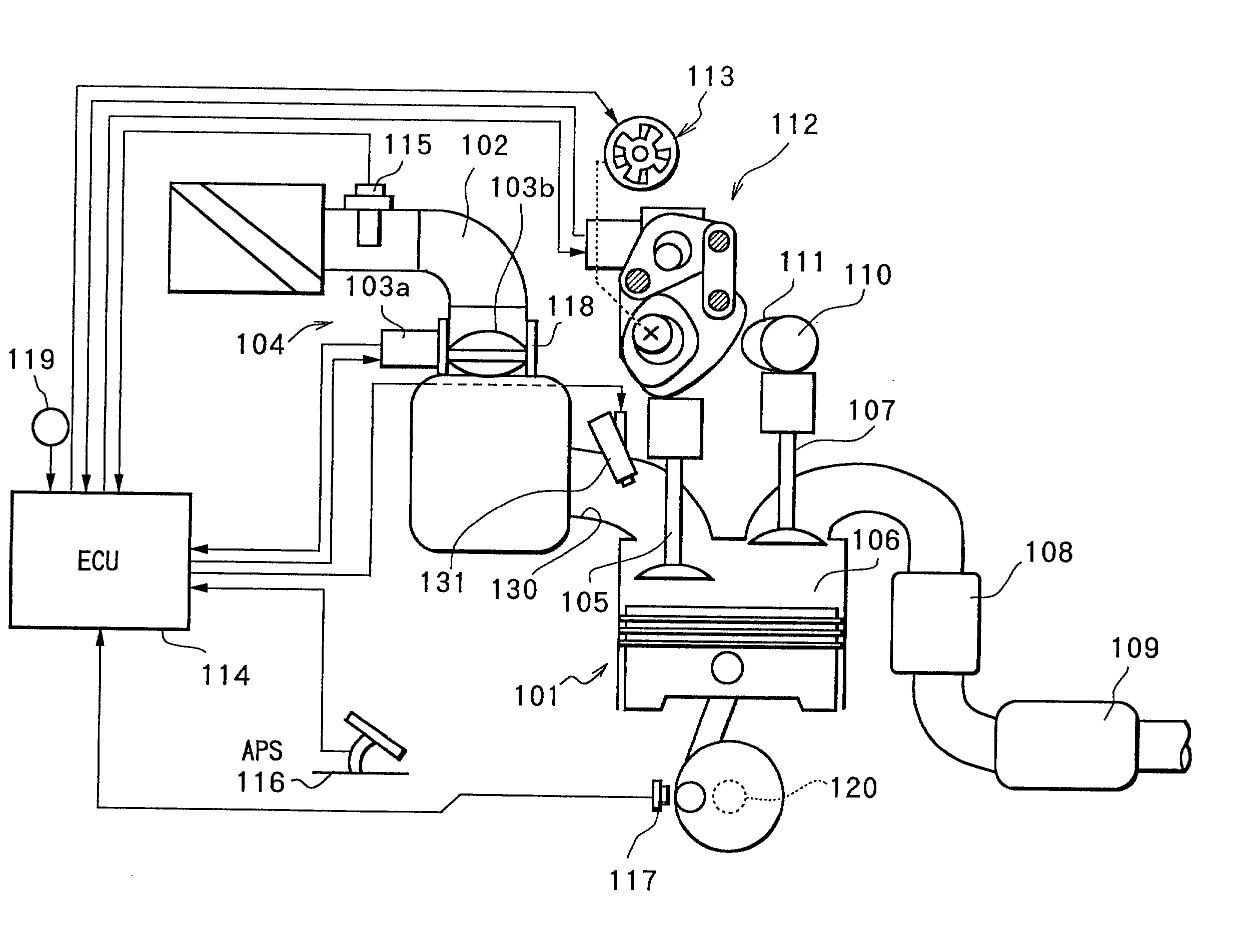
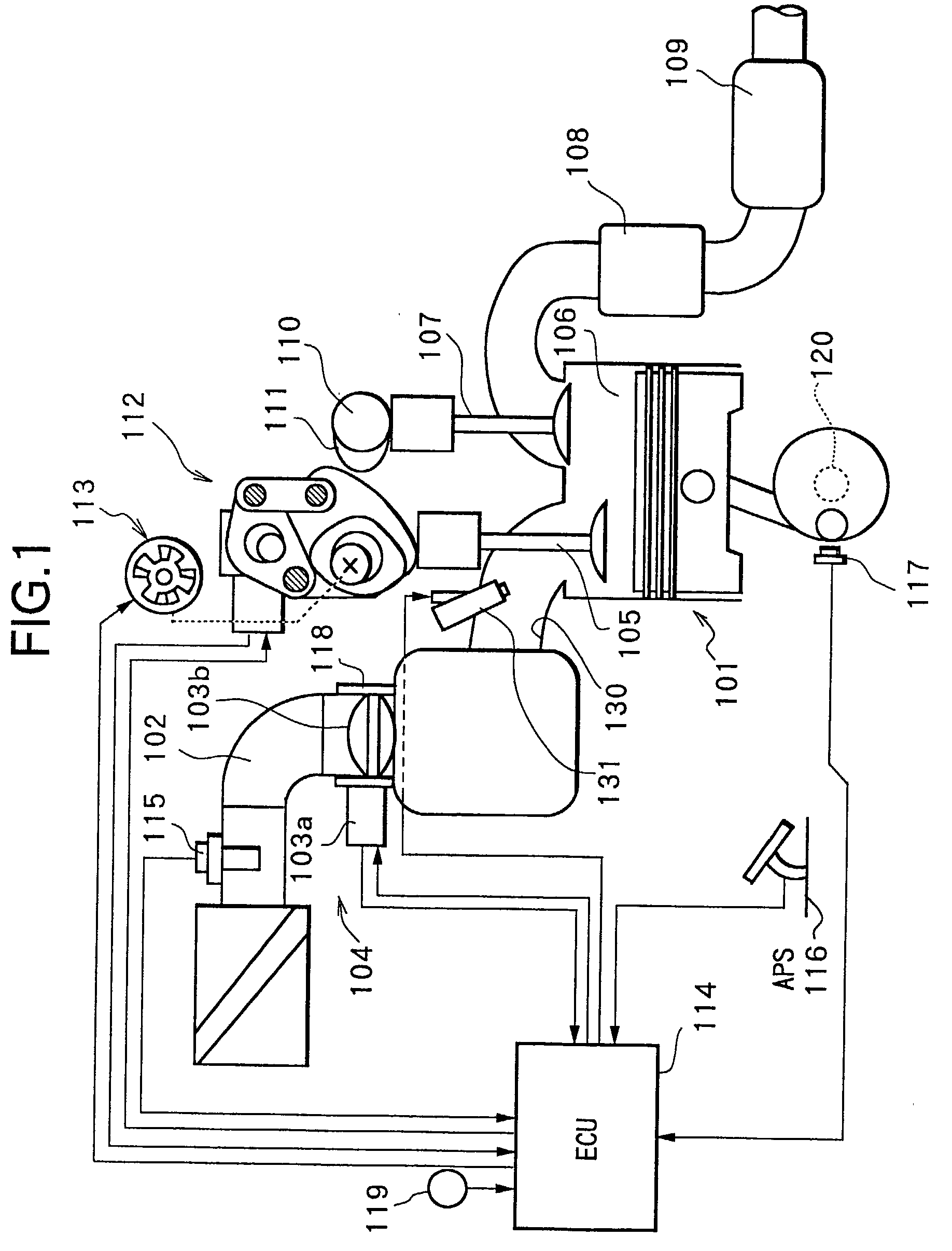
[0085] In the constitution as mentioned in the above, there will be described in detail an intake air amount control executed by control unit (C / U) 114, that is a control on electronically controlled throttle 104, variable valve mechanism (VEL) 112 and variable valve timing mechanism (VTC) 113 (a first embodiment).

[0086] As shown in FIG. 12, control unit (C / U) 114 includes a target volume flow ratio calculating section "a", a VTC target operating angle calculating section "b", a VEL target operating angle calculating section "c" and a target throttle opening calculating section "d".

[0087] (a) Calculation of Target Volume Flow Ratio TQH0ST

[0088] The target volume flow ratio calculating section "a" calculates a target volume flow ratio TQH0ST equivalent to a target torque as follows.

[0089] Firstly, a requested air amount (a requested engine air amount) Q0 corresponding to accelerator opening APO and engine rotation speed Ne (or, that so as to obtain a target torque set based on accele...

second embodiment

[0177] Next, other embodiment (second embodiment) of intake air amount control to be executed by control unit (C / U) 114 will be described with reference to block diagrams of FIG. 21 to FIG. 24.

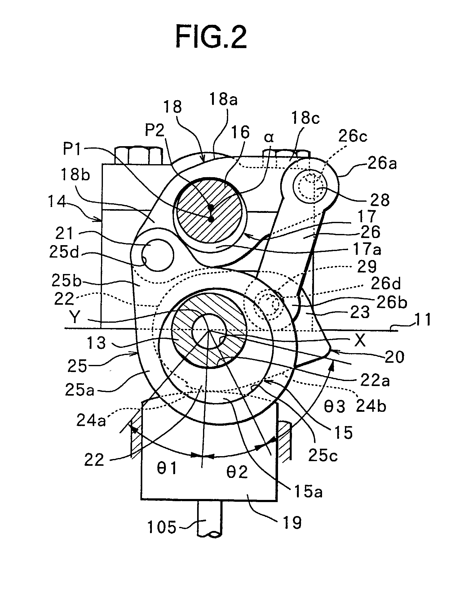
[0178] In this embodiment, intake valve 105 is controlled to a target valve operating characteristic. While, in a total opening area (an integrated value of opening areas) obtained based on the target valve operating characteristic, since the opening area during valve overlap period is an ineffective portion where air is not newly sucked, the total opening area is corrected with a correction value according to the valve overlap to be made a total opening area (effective opening area) where air is newly sucked, so that the total opening area (effective opening area) indicative of intake air amount actually controlled by intake valve is compared with the target intake air amount to set a target opening of throttle valve 103b.

[0179] In FIG. 21, a target volume flow ratio calculating section 301 c...


PUM


Abstract

In an internal combustion engine provided with a variable valve mechanism that varies at least a valve operating characteristic (valve lift amount, valve operating angle and the like) of an intake valve, a target volume flow ratio equivalent to a target torque of the engine is obtained to be converted into a valve opening area, and a target valve operating characteristic of the variable valve mechanism is set based on the converted valve opening area, to control the variable valve mechanism so that an actual valve operating characteristic reaches a target valve operating angle, thereby executing with high accuracy an intake air amount control mainly by the variable valve mechanism.

Description

[0001] The present invention relates to a technique for controlling an intake air amount by a variable valve mechanism in an engine, which varies at least an operation characteristic of an intake valve.RELATED ART OF THE INVENTION[0002] Heretofore, there has been known a variable valve mechanism constituted to successively vary a valve lift amount and a valve operating angle (refer to Japanese Unexamined Patent Publication 2001-012262).[0003] In an engine provided with such a variable valve mechanism, a valve lift amount and a valve operating angle are controlled by the variable valve mechanism, to control an intake air amount independently of a throttle valve. However, in this case, since a torque control by the throttle valve cannot be performed, there occurs a problem of how the torque linearity is ensured.[0004] Further, in the case where the intake air amount control is performed by the above variable valve mechanism, it is impossible to generate, in an intake air passage, a ne...

Claims


Application Information

Patent Timeline
Patent Type & Authority Applications(United States)
IPC IPC(8): F02D13/02
CPCY02T10/18F02D13/0226Y02T10/12
Inventor MACHIDA, KENICHISHIMIZU, HIROKAZUIIZUKA, ISAMU
Owner HITACHI ASTEMO LTD
Why Eureka
Try Eureka