Intake air control system for internal combustion engine

a control system and air intake technology, applied in the direction of electric control, speed sensing governors, instruments, etc., can solve the problems of difficult to maintain the rotational speed of the engine rotational speed of the target engine, and achieve the effect of stabilizing the engine rotation

Inactive Publication Date: 2010-08-10
HONDA MOTOR CO LTD
View PDF9 Cites 2 Cited by
  • Summary
  • Abstract
  • Description
  • Claims
  • Application Information

AI Technical Summary

Benefits of technology

[0007]The present invention was made by contemplating the above-described points, and an object of the invention is to provide an intake air control system for an internal combustion engine, which implements a smooth shift to the idling condition from an operating condition other than the idling condition, thereby stabilizing the engine rotation in the idling condition
[0009]With the above-described structural configuration, when the engine is determined to be in the idling condition the command value of the lift amount of the intake valve is calculated according to the target engine rotational speed and the target intake air flow rate set for the idling condition. The valve operating characteristic varying mechanism is controlled according to the lift amount command value. That is, since control of the intake air flow rate in the idling condition is performed by varying the lift amount of the intake valve, there is no switching of control between the intake and throttle valves as is performed in the previously described conventional system. This aspect enables the engine to shift smoothly to the idling condition. Further, if the lift amount of the intake valve is varied according to the detected engine rotational speed, it is difficult to maintain the engine rotational speed of the target engine rotational speed. By calculating the lift amount command value according to the target engine rotational speed, the engine rotational speed in the idling condition is stably maintained at the target engine rotational speed.

Problems solved by technology

Further, if the lift amount of the intake valve is varied according to the detected engine rotational speed, it is difficult to maintain the engine rotational speed of the target engine rotational speed.

Method used


Image

  • Intake air control system for internal combustion engine
  • Intake air control system for internal combustion engine
  • Intake air control system for internal combustion engine

Examples


Embodiment Construction

[0022]Preferred embodiments of the present invention will now be described with reference to the drawings.

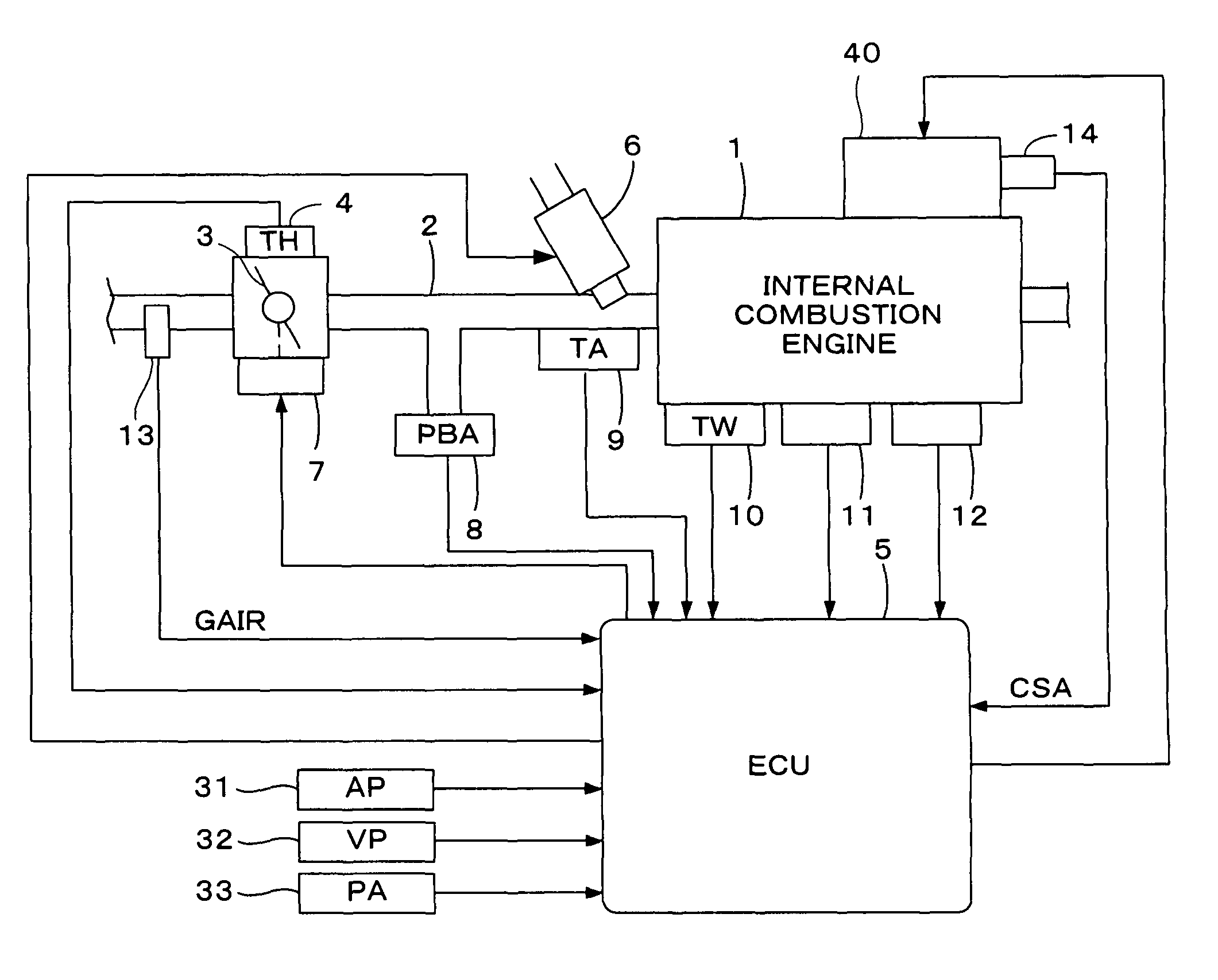
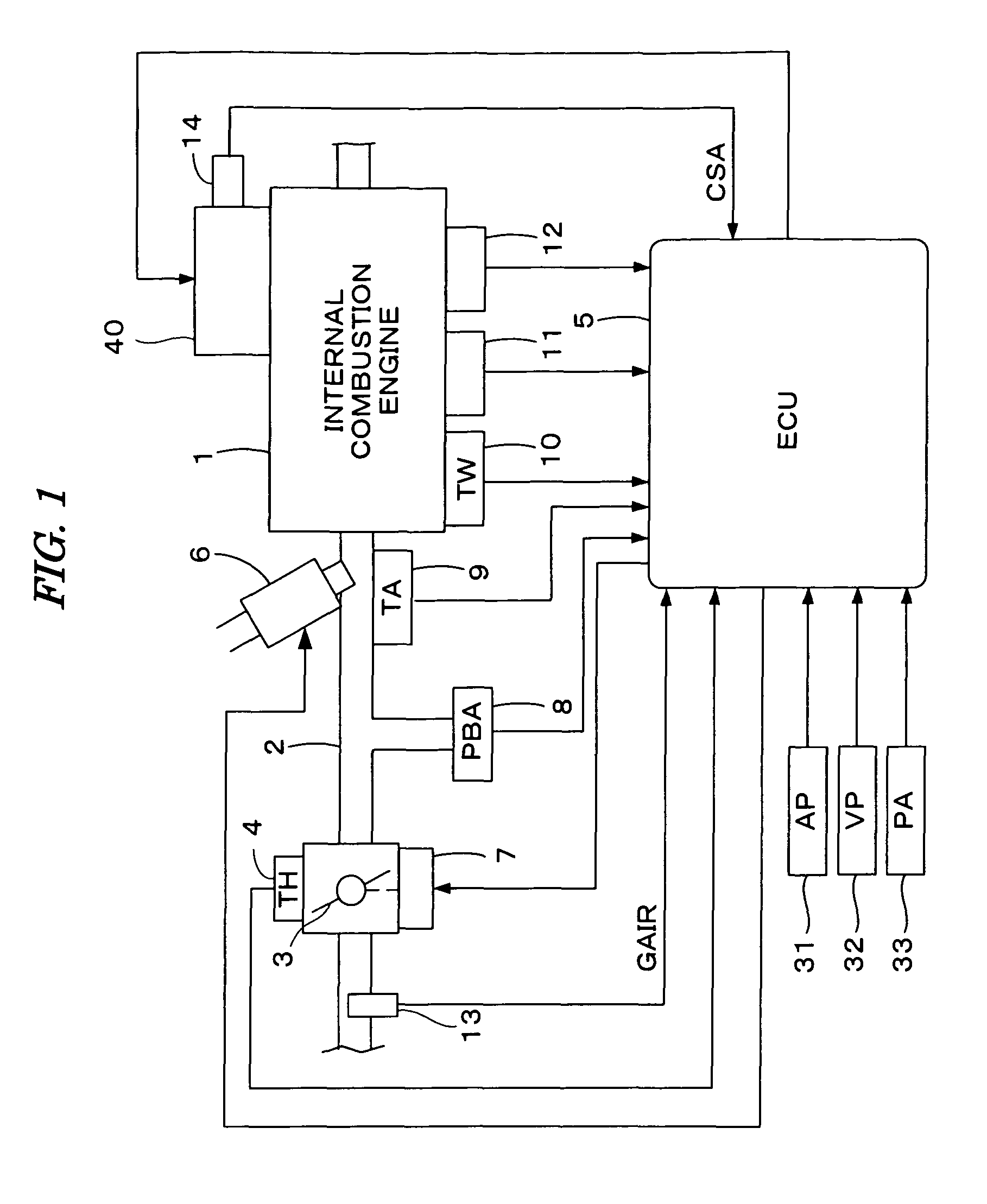
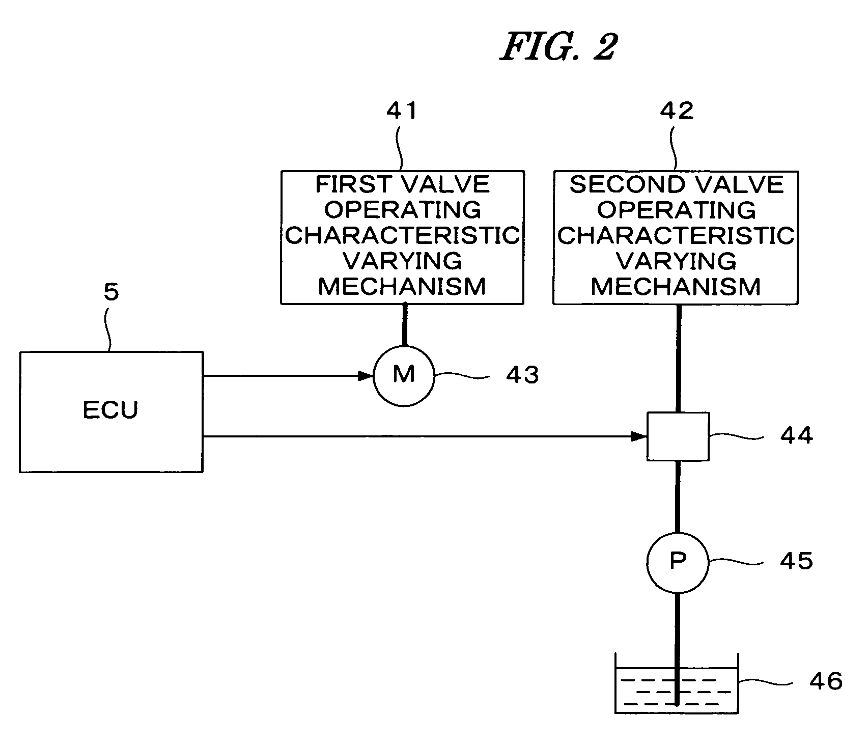
[0023]FIG. 1 is a schematic diagram of an internal combustion engine and a control system according to an embodiment of the present invention, and FIG. 2 is a schematic diagram of a valve operating characteristic varying device. Referring to FIG. 1, an internal combustion engine 1 (hereinafter referred to as “engine”), having, for example, four cylinders, is provided with intake valves, exhaust valves, and cams for driving the intake valves and the exhaust valves. The engine 1 is provided with a valve operating characteristic varying device 40, having a first valve operating characteristic varying mechanism 41, and a second valve operating characteristic varying mechanism 42. The first valve operating characteristic varying mechanism 41 continuously varies the valve lift amount and the opening angle (valve opening period) of the intake valve. The second valve operating character...


PUM


Abstract

An intake air control system for an internal combustion engine having at least one intake valve and a valve operating characteristic varying mechanism which continuously varies a lift amount of the at least one intake valve of the engine. A target intake air flow rate of the engine is calculated along with a command value of the lift amount according to a target engine rotational speed set in an idling condition of the engine and the target intake air flow rate when the engine is determined to be in an idling condition. The valve operating characteristic varying mechanism is controlled according to the calculated lift amount command value.

Description

BACKGROUND OF THE INVENTION[0001]1. Field of the Invention[0002]The present invention relates to an intake air control system for an internal combustion engine, and particularly to an intake air control system for an internal combustion engine having a valve operating characteristic varying mechanism for continuously varying a lift amount of at least one intake valve of the engine.[0003]2. Description of the Related Art[0004]Japanese Patent Laid-open No. 2005-171793 (JP '793) discloses a control system for an internal combustion engine having a valve operating characteristic varying mechanism for continuously varying a lift amount of intake valves and an electronically-controlled throttle valve. According to the conventional system disclosed in JP '793, in an engine operating condition other than an idling condition and a high-load operating condition, an intake air amount of the engine is controlled by varying the lift amount of the intake valve (a valve operating angle). If the id...

Claims


Application Information

Patent Timeline
Patent Type & Authority Patents(United States)
IPC IPC(8): F02D13/00F02D13/04
CPCF02D31/003F02D41/0002F02D41/083F02D2041/001Y02T10/42Y02T10/18Y02T10/12Y02T10/40
Inventor TAKAMIYA, HIDEHARUKOMORIYA, ISAO
Owner HONDA MOTOR CO LTD
Why Eureka
Try Eureka