Variable pneumatic door control system

A valve control system and valve technology, applied to non-mechanically actuated valves, engine components, machines/engines, etc., can solve the problems of complex system structure, unsatisfactory response speed, and high energy consumption.

Inactive Publication Date: 2007-05-09
NINGBO HOYEA MACHINERY MFG
View PDF1 Cites 3 Cited by
  • Summary
  • Abstract
  • Description
  • Claims
  • Application Information

AI Technical Summary

Problems solved by technology

Although the system uses a differential pressure proportional pressure reducing valve to replace the previous reversing valve combined with a displacement sensor and other devices to control the lift and timing of the valve at any time as

Method used


Image

  • Variable pneumatic door control system

Examples


Embodiment

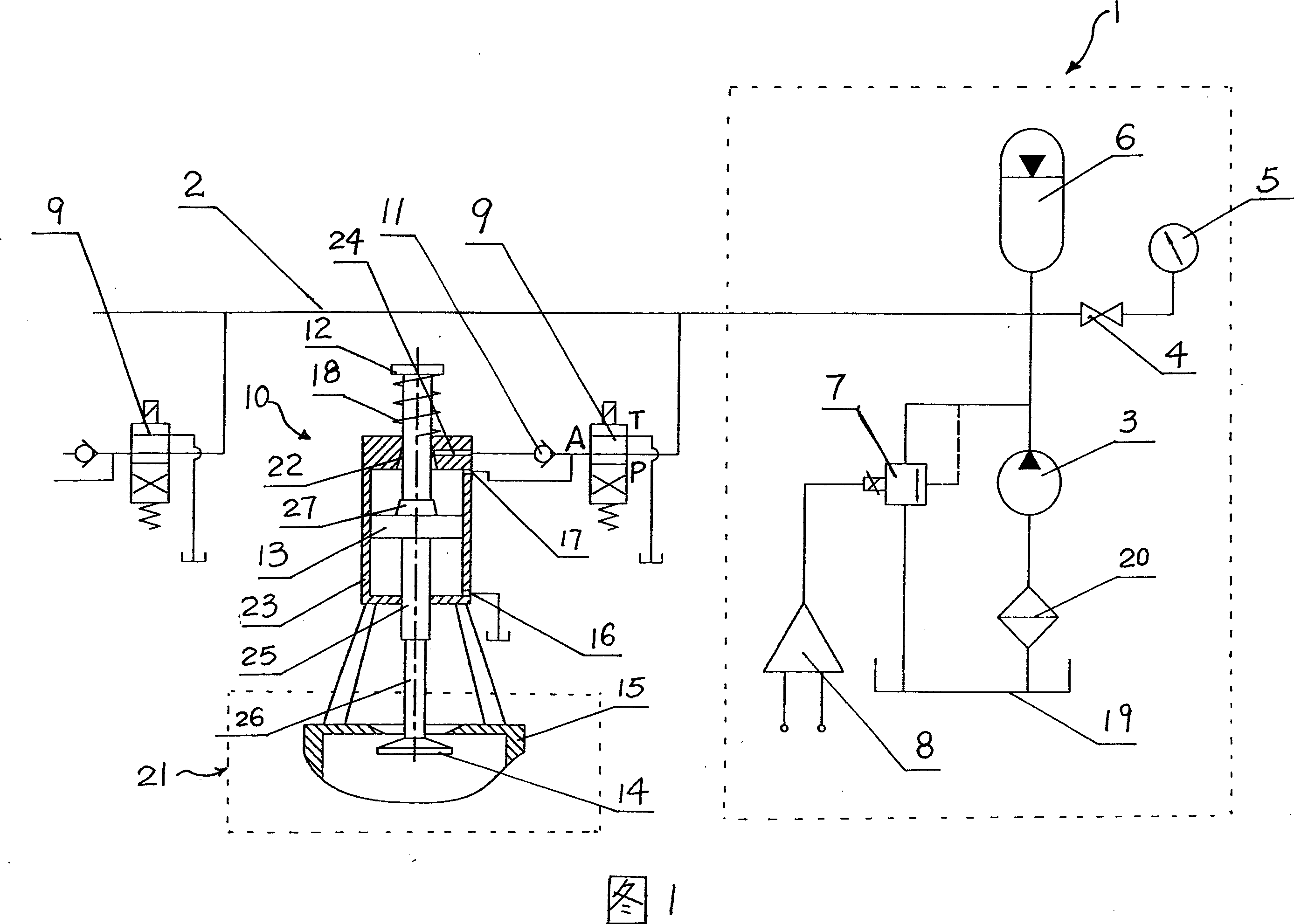
[0019] Accompanying drawing 1 is a schematic diagram of an embodiment of the present invention. As shown in FIG. 1 , the control system of the present invention is mainly composed of a hydraulic supply system 1 , a high-speed switching valve 9 , a hydraulic actuator 10 and an air valve 21 . The hydraulic supply system 1 is composed of an oil pump 3 , an oil tank 19 , an oil filter 20 , a controller 8 and a proportional pressure valve 7 . The controller 8 selects a proportional amplifier, and the proportional pressure valve 7 selects a proportional overflow valve. The oil inlet of the oil pump 3 communicates with the fuel tank 19 through the oil filter 20 , and the oil outlet of the oil pump 3 is connected to the main oil pipe 2 . The total oil inlet pipe 2 is equipped with a pressure accumulator 6, a pressure gauge switch 4 and a pressure gauge 5. The output end of the proportional amplifier 8 is connected with the electromagnet of the proportional overflow valve 7, the oil ...


PUM


Abstract

A control system of variable air door consists of air door, hydraulic actuating element connected with air door, hydraulic-supplying unit and controller. It is featured as connecting hydraulic cylinder to general oil tube through high speed switch valve, setting proportional pressure valve between general oil tube and oil box, connecting electromagnetic iron of proportional pressure valve to controller and connecting high speed valve of hydraulic cylinder with oil box.

Description

technical field [0001] The invention relates to a control system of an internal combustion engine valve, in particular to the improvement of a control system of a differential pressure variable valve. Background technique [0002] The present invention is an improvement to the Chinese invention patent (patent application number: 200310108911.8) applied by the applicant. and the spring for controlling the balance of the piston. The hydraulic actuator includes a hydraulic cylinder, a piston and a piston rod. The piston rod is linked with the valve. The piston divides the hydraulic cylinder into an upper chamber and a lower chamber. The hydraulic supply device communicates with the upper chamber of the hydraulic cylinder through the main oil inlet pipe, and it is characterized in that: the hydraulic supply device is also connected with the oil inlet port of the pressure difference proportional pressure reducing valve through the main oil inlet pipe, and the pressure difference ...

Claims


Application Information

Patent Timeline
IPC IPC(8): F01L9/02F01L9/10
Inventor 凌俊杰翁振涛
Owner NINGBO HOYEA MACHINERY MFG
Why Eureka
Try Eureka