variable valve timing method

A valve timing and variable technology, applied in valve devices, machines/engines, mechanical equipment, etc., can solve the problems of increasing the weight of the whole machine, the power output is not linear enough, and the actuators are complex, so as to reduce the overall weight and versatility. Strong, responsive effects

Active Publication Date: 2016-03-02
HANGZHOU BRANCH ZHEJIANG GEELY AUTOMOBILE RES INST +2
View PDF7 Cites 0 Cited by
  • Summary
  • Abstract
  • Description
  • Claims
  • Application Information

AI Technical Summary

Problems solved by technology

However, the application defect of this technology is that the mechanism is complex and the power output is not linear enough.
Other continuously variable valve lift technologies, although the smoothness of power output has been improved, but the actuators are more complex
[0004] Comprehensive analysis of several variable valve lift technologies on the market, all of which use the camshaft as the power source to drive complex kinematic pairs and change the valve lift through mechanical movement. Such mechanisms are complex in structure and have many parts, which will inevitably increase the Weight; the movement is cumbersome, which inevitably causes friction loss; too many positions need cooling and lubrication, which has almost strict requirements on the design of the oil circuit; in order to assemble this mechanism, the cylinder head system needs to be modified in a large area, and the versatility is poor

Method used


Image

  • variable valve timing method
  • variable valve timing method
  • variable valve timing method

Examples


Embodiment Construction

[0047] The present invention will be further described in detail below in conjunction with the accompanying drawings and specific embodiments.

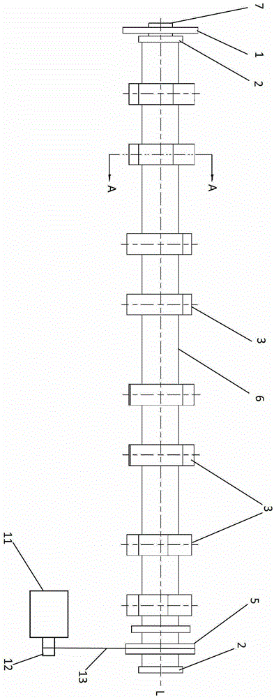
[0048] figure 1One embodiment of the variable valve timing device of the present invention for controlling the opening and closing timing of valves of a vehicle engine is shown. The variable valve timing device includes a camshaft 6 . Several cams 3 are arranged on the camshaft 6, and the opening and closing of the engine valves (not shown) are driven by the cams 3 when the camshaft 6 rotates.

[0049] A rotary drive member 7 is used to drive the camshaft 6 . A timing sprocket 1 is arranged on the rotating driving part 7, and the timing sprocket 1 is connected with the crankshaft of the engine through a timing chain or a timing belt (not shown). In this way, the rotary driving part 7 can rotate synchronously with the crankshaft driven by the crankshaft of the engine.

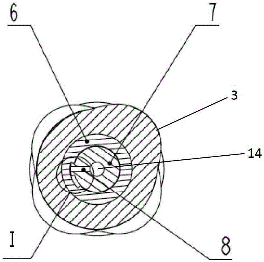
[0050] combine figure 1 with figure 2 To see more clearly, ...


PUM


Abstract

The invention discloses a variable valve timing method used for controlling opening and closing timing of a valve of a vehicular engine. When the valve needs to be opened in advance, a phase adjusting mechanism drives a camshaft to rotate forwards relative to a rotary driving part; when the camshaft rotates to a position enabling the valve to be maximum in lift basically, the phase adjusting mechanism keeps the camshaft at the current position, so that the valve is kept at the maximum lift basically; and after the camshaft is kept at the current position for a period of preset time, the rotary driving part drives the camshaft to rotate continuously. The valve can be opened continuously by the variable valve timing method, and the variable valve timing method is larger in air inflow as compared with that in the prior art under the high-rotational-speed high-load working condition.

Description

technical field [0001] The present invention relates to the automotive field, and more particularly, to variable valve timing methods. Background technique [0002] It is known from the prior art that the higher the engine speed, the shorter the intake time of the cylinder in one working cycle. At high speed and heavy load, more air intake is required to improve the combustion efficiency of the engine, so that the engine has a higher power output; Achieve good fuel economy. Therefore, more and more vehicle engines use variable valve timing (VVT) technology to change the valve timing of the intake and exhaust valves. [0003] The traditional VVT technology can improve the power and fuel economy of the engine to a certain extent by adjusting the opening of the valve in advance, but the valve timing system does not change the duration of the valve opening, and the intake air volume per unit time does not improve much, so for The performance of the engine doesn't help much ei...

Claims


Application Information

Patent Timeline
Patent Type & Authority Patents(China)
IPC IPC(8): F01L1/348
Inventor 苏相楠由毅沈源刘岩赵福全
Owner HANGZHOU BRANCH ZHEJIANG GEELY AUTOMOBILE RES INST
Why Eureka
Try Eureka