
Detection method for cylinder deactivation camshaft displacement

A detection method and camshaft technology, applied in the direction of measuring devices, optical devices, instruments, etc., can solve the problems of engine cylinder deactivation technology without effective detection methods, and achieve the effect of ensuring product quality

Active Publication Date: 2019-01-15
ANHUI JIANGHUAI AUTOMOBILE GRP CORP LTD
View PDF8 Cites 0 Cited by
  • Summary
  • Abstract
  • Description
  • Claims
  • Application Information

AI Technical Summary

Problems solved by technology

[0006] The purpose of the present invention is to provide a detection method for camshaft displacement of cylinder deactivation to solve the problem that the existing engine cylinder deactivation technology has no effective detection means

Method used


Image

  • Detection method for cylinder deactivation camshaft displacement
  • Detection method for cylinder deactivation camshaft displacement
  • Detection method for cylinder deactivation camshaft displacement

Examples


Embodiment Construction

[0040] The technical solution of the present invention is described in detail below through the examples, and the following examples are only exemplary and can only be used to explain and illustrate the technical solution of the present invention, rather than being interpreted as a limitation to the technical solution of the present invention.

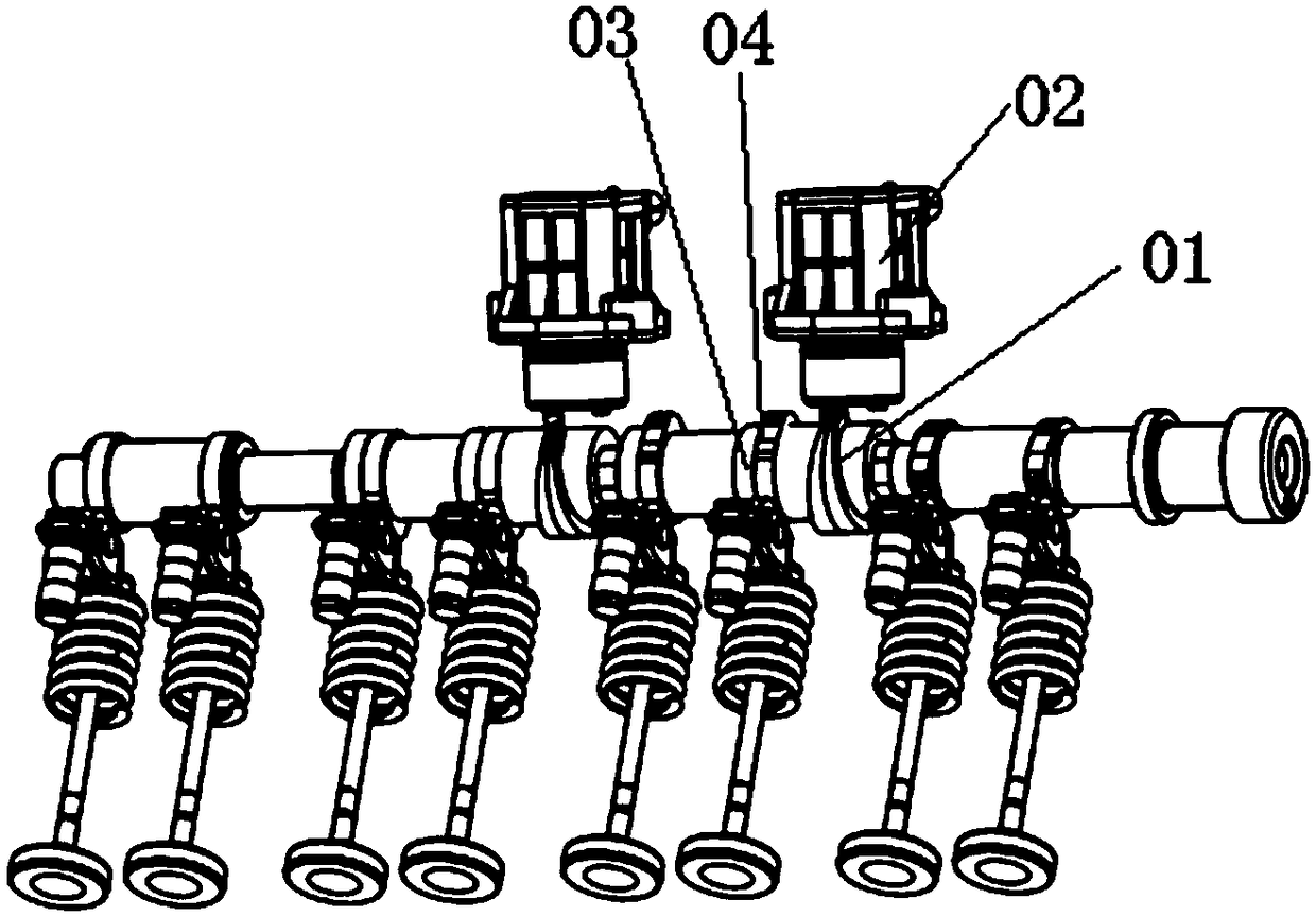
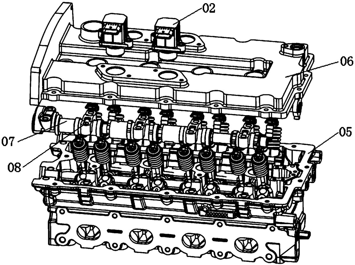
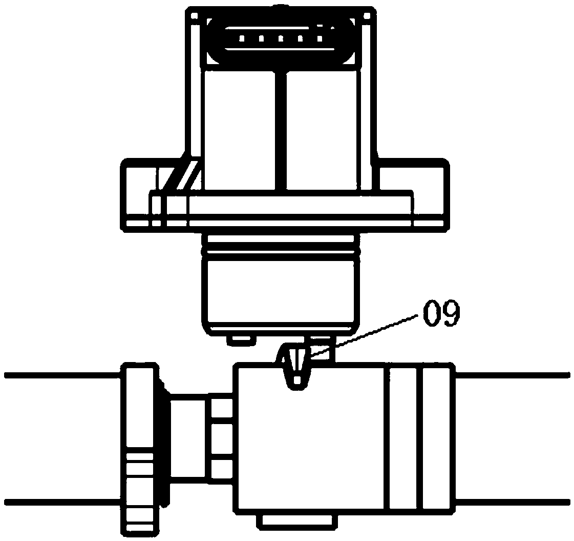
[0041] This application provides a test that can effectively detect the state of the rotation groove of the camshaft sleeve. On the one hand, the test result can be used to judge whether the cylinder head camshaft after assembly is qualified. On the other hand, the test result can be used as a control strategy for the solenoid valve pin input signal.

[0042] Such as Figure 4 to Figure 7 As shown in the static displacement detection method, the product 101 to be tested is fixed on the test platform, and the high-definition camera 102 is fixed by the tripod 103 . The tripod can be adjusted in height and angle. The displacement accurac...


PUM


Abstract

The invention relates to a detection method for a cylinder deactivation camshaft displacement. The detection method comprises a static displacement detection method and a dynamic displacement detection method. According to the detection method, the form of a rotation groove of the camshaft sleeve can be effectively detected, and the product assembly quality is effectively controlled through detection. The cam sleeve can be detected in real time by the method for dynamically detecting the displacement when used by a terminal client, stopping the working of the valve pin of the solenoid valve and informing a failure when the sleeve is stuck, thereby preventing that the valve pin extends and collides with the camshaft sleeve to cause an engine fault; or informing the fault in time to remind the client for maintenance and replacement when the wear of the rotating groove of the camshaft sleeve is excessive.

Description

technical field [0001] The invention belongs to the technical field of engine detection, in particular to a detection method for the displacement of a cylinder-deactivated camshaft. Background technique [0002] Against the background of increasingly stringent fuel consumption standards, auto companies are facing increasing pressure to save fuel. At the same time, the state has issued a series of policies such as the conversion of energy consumption of new energy vehicles, the limit of pure electric power consumption, and the reduction of the weighting factor of BEV sales. Traditional vehicles are under great pressure to save fuel. For fuel vehicles, in principle, there are two main technical directions to achieve fuel saving through the engine: one is to improve the thermal efficiency of the engine; the other is to allow the engine to run at a lower fuel consumption point through load control, such as supercharging technology, Cylinder deactivation technology, etc. Among ...

Claims


Application Information

Patent Timeline
Patent Type & Authority Applications(China)
IPC IPC(8): G01B11/02
CPCG01B11/028
Inventor 陈龙华王锦艳颜伟李海鹏张鑫
Owner ANHUI JIANGHUAI AUTOMOBILE GRP CORP LTD
Learn More