
Control device for variable valve actuation system
a control device and valve timing technology, applied in the direction of electrical control, process and machine control, instruments, etc., can solve the problems of engine valve interference with the piston, difficulty in appropriately avoiding valve stamping, and possible error in the reference operating position of the variable valve timing mechanism
- Summary
- Abstract
- Description
- Claims
- Application Information
AI Technical Summary
Benefits of technology
Problems solved by technology
Method used
Image

Examples
Embodiment Construction
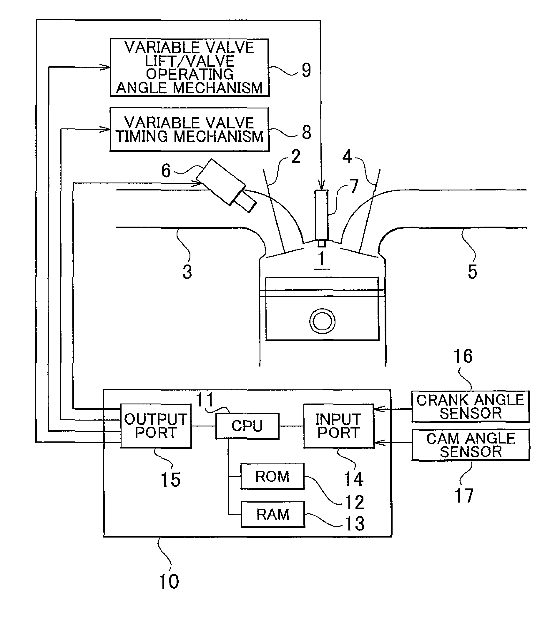
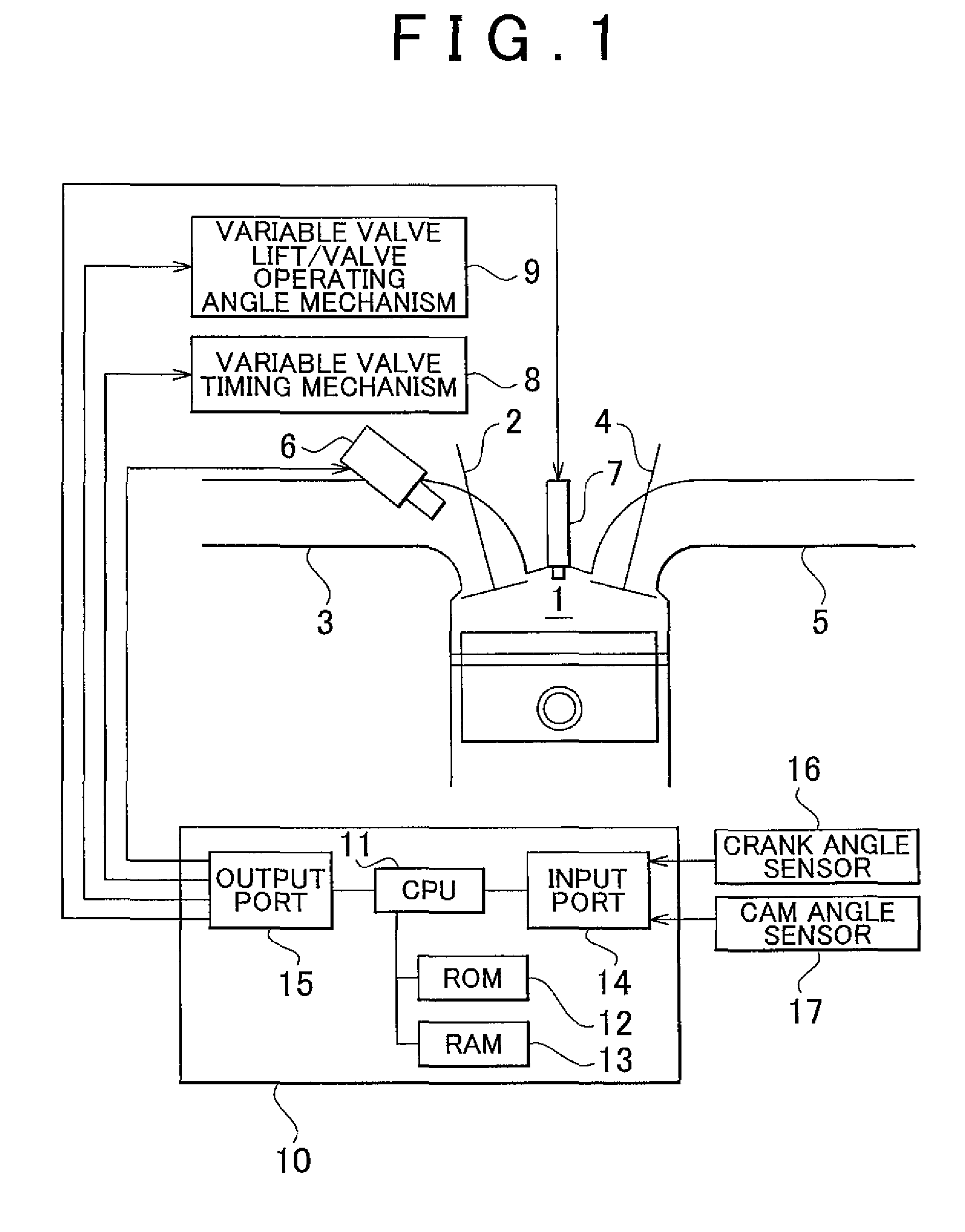
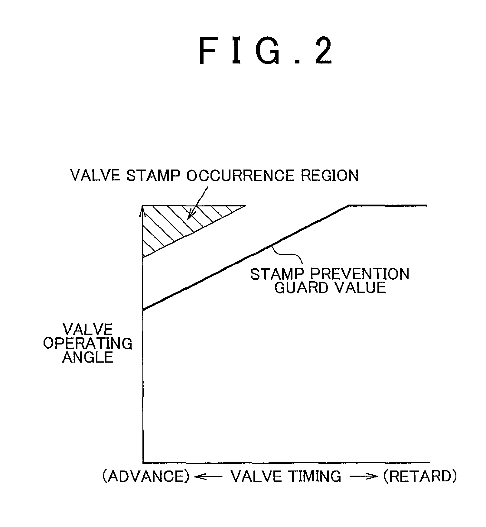
Hereinafter, a control device for a variable valve actuation system according to an embodiment of the invention will be described in detail with reference to FIG. 1 to FIG. 3. FIG. 1 shows the configuration of an internal combustion engine to which the control device for a variable valve actuation system according to the embodiment is applied and also shows the control system of the internal combustion engine.
A combustion chamber 1 of the internal combustion engine according to the embodiment is coupled to an intake pipe 3 via an intake valve 2, and is coupled to an exhaust pipe 5 via an exhaust valve 4. An injector 6 is provided for the intake pipe 3. The injector 6 injects fuel into intake air flowing through the intake pipe 3. In addition, an ignition plug 7 is provided in the combustion chamber 1. The ignition plug 7 ignites a mixture of air and fuel introduced into the combustion chamber 1.
In a valve actuation system for the intake valve 2 of the thus configured internal combus...
PUM
 Abstract
Description
Claims
Application Information