
Voice over IP architecture

a voice over internet protocol and voice technology, applied in the field of telecommunications system architectures, can solve the problems of increasing the cost of voice services in the telecommunications market, the cost of developing voice service networks, and the inability to meet the needs of voice services

Active Publication Date: 2003-04-24
AVAGO TECH INT SALES PTE LTD
View PDF4 Cites 327 Cited by
  • Summary
  • Abstract
  • Description
  • Claims
  • Application Information

AI Technical Summary

Problems solved by technology

Increased competition among existing and emerging voice service vendors has brought tremendous downward pressure on the cost of voice services in the telecommunications market.
Building a parallel voice services network based on legacy circuit-switching equipment is simply not a cost-effective option.
Many emerging competitive local exchange carriers (CLECs) are sensitive to the cost of developing voice service networks.
For many, the cost of legacy voice circuit-switching equipment is prohibitively high.
Also the cost of the space, personnel, and operations capabilities required to maintain such networks is prohibitive.
The processes used to convert, compress, and otherwise manipulate voice data in digital form are numerous and complex.
H.323 specifications tend to be heavy handed and initially focused on LAN networking.
One H.323 scalability issue is its dependency on TCP-based (connection-oriented) signaling.
It is difficult to maintain large numbers of TCP sessions because of the greater overhead involved.
This protocol does not have good scaling properties due to its focus and management of individual application traffic flows.
For these and other reasons, H.323 has historically been deemed ill-suited for service provider applications, and has been relegated to enterprise VoIP applications.
The call agent and media gateways typically have retransmission facilities for these messages, but the MGCP itself is stateless.
Hence, one of the great challenges to implementing SIP services is mapping CoS delivery for the signaling and bearer traffic.
Its infrastructure costs too much and is not capable of delivering the telecommunication services demanded by today's customers.
TDM equipment simple can not support the modem packet-based transmission technologies required to provide these services.
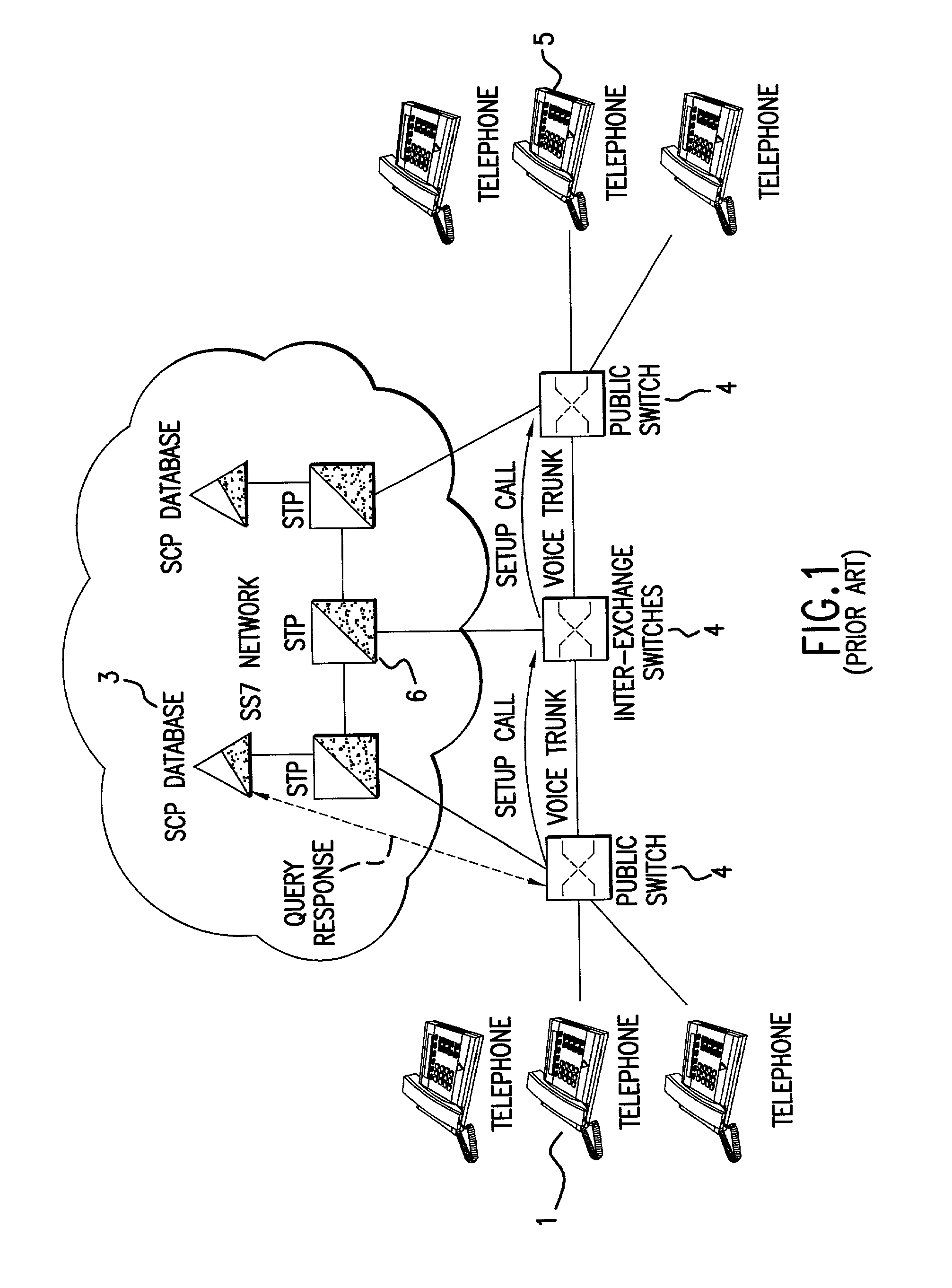
Unfortunately, the capital investment made by service providers in the PSTN is immense.
Because of the call-by-call signaling approach taken and with the historic functional boundaries established between conventional VoIP components, session data is inefficiently stored and utilized.

Method used


Image

  • Voice over IP architecture
  • Voice over IP architecture
  • Voice over IP architecture

Examples


Embodiment Construction

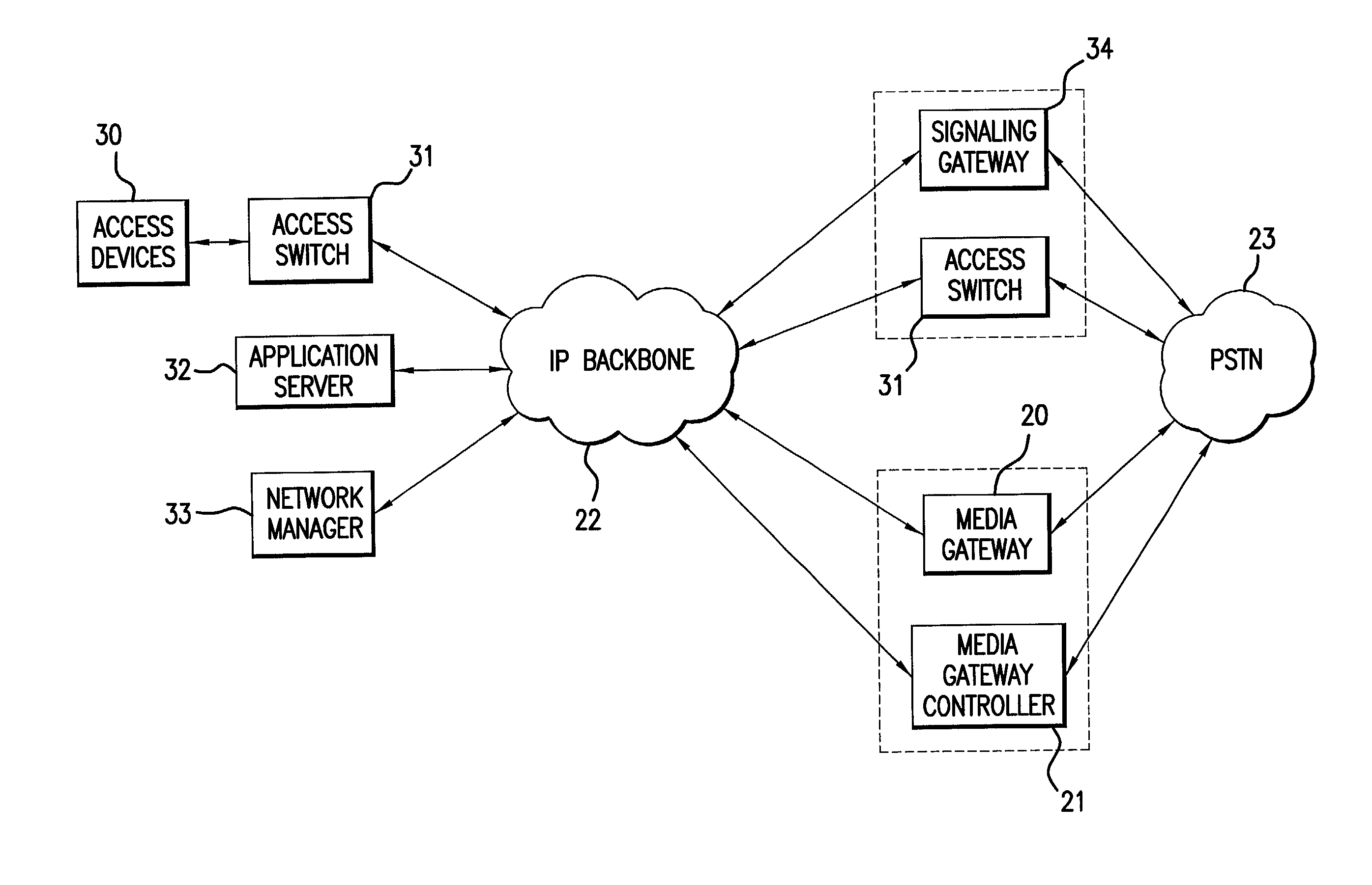
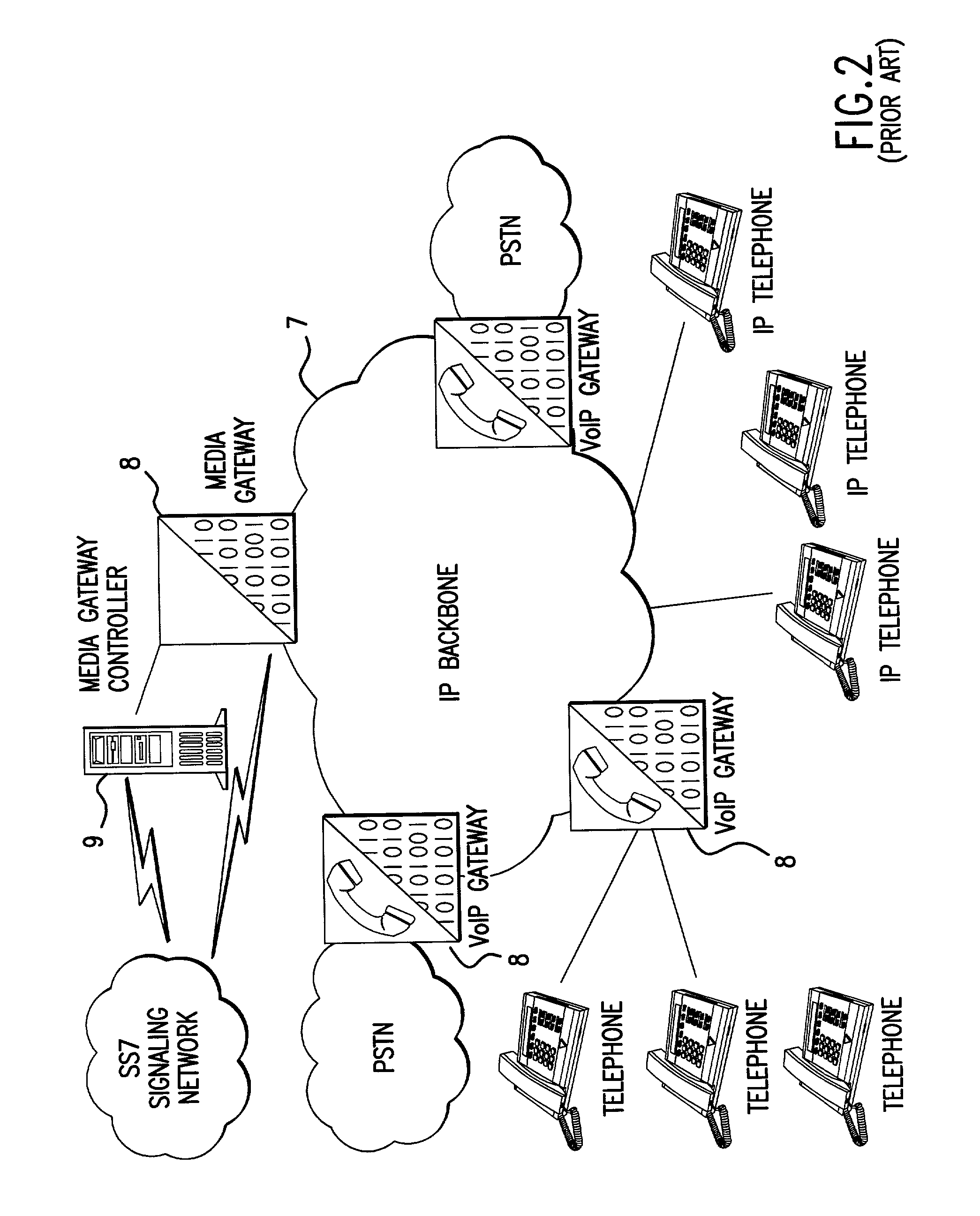
[0081] Conventional VoIP architectures are largely based on two elements, the Media Gateway Controller (MGC), sometimes referred to as a softswitch, and the Media Gateway (MG), also referred to as a trunking gateway. FIG. 5 illustrates the relationship of Media Gateway 20 and the Media Gateway Controller 21 as components bridging a VoIP network 22 and the PSTN 23. The functional roles of these two components have previously been described. In short, the combination of a MG and a MGC can be used to move packetized payload and signaling data between VoIP network 22 and PSTN 23. Media Gateway 20 can be used to convert packetized voice data into TDM voice for transmission over the PSTN. Media Gateway Controller 21 can be used both to control operation of Media Gateway 20 and inter-operate with the signaling components of the PSTN.

[0082] Unfortunately, the conventional combination of a MG and a MGC suffers from a number of difficulties, including poor (or weak) signaling protocols, and s...


PUM


Abstract

A Voice over Internet Protocol (VoIP) network is described in which session state is maintained in access switches, but not signaling gateways which maintain transaction state only during pendency of a related transaction. The signaling gateway further provides transparent inter-operation between the VoIP network and non-IP networks, such as the PSTN, by means of a translator which directly translates messages between the networks.

Description

[0001] This application claims the benefit of U.S. Provisional Application No. 60 / 330,330 filed Oct. 19, 2001[0002] 1. Field of the Invention[0003] The present invention relates to telecommunications system architectures, and more specifically to Voice over Internet Protocol (VoIP) architectures. Improved access methodologies and system components, including an access switch and signaling gateway, are described within the context of a novel VoIP architecture. These improved system components and methodologies manage session state more efficiently and provide a clear migration path from conventional system architectures.[0004] 2. Description of the Related Art[0005] Although VoIP has been in existence for many years, evolving service demands are forcing a rapid evolution of VoIP technology. The pace at which new services are being integrated into existing networks continues to increase as VoIP products and services develop.[0006] Though still evolving, packet-based telephony is becom...

Claims


Application Information

Patent Timeline
IPC IPC(8): H04L12/56H04M7/00H04Q3/00
CPCH04L49/205H04L49/602H04Q3/0025H04M7/1255H04M7/127H04M7/0093
Inventor MILLER, FRANK WILLIAMSIPPER, AARON JIP
Owner AVAGO TECH INT SALES PTE LTD
Learn More