Transport device for hauling a load

a technology for transporting devices and loads, applied in the field of transport devices, can solve the problems of inconvenient maintenance operations, the thickness of the elongated ladder frame, and the amount of liquid that can be pumped out of the tank

Inactive Publication Date: 2003-05-15
COLET RALPH
View PDF0 Cites 12 Cited by
  • Summary
  • Abstract
  • Description
  • Claims
  • Application Information

AI Technical Summary

Problems solved by technology

One limitation is that the elongated ladder frame must have a thickness (weight of the frame) sufficiently great to prevent excessive flexion of the frame.
A second limitation is that the arrangement of the tank and motor on top of the frame on top of leaf springs on top of the axle mandates that the center of gravity of the loaded truck is at a height above the ground that the tendency of the truck to roll over becomes an important consideration in terms of safe driving practices such as speed around curves, allowable tilt when driving on road beds that are not level, etc.
A third limitation is the amount of liquid that can be pumped out of the tank when the tank is tilted on an incline or decline.
A fourth limitation is the inconvenience of performing maintenance operations particularly operations requiring temporarily dismounting of the motor that is located at an elevated height on top of the frame.
A fifth limitation is the inherent characteristic that a large fraction of the truck structure, the tank, makes no contribution to the structural strength of the truck and is subject to severe flexion because of its elongated oblong shape.
A sixth limitation is operative when applied to Military uses of the truck according to which the overall height and length and width of the truck and weight when fully loaded are all limited by the requirement that the truck be capable of being transported on an airplane, particularly the air force C130.
The design of this vehicle is characterized by minimizing bending moments that otherwise lead to at least unsafe driving conditions and, at worst, to failure of structural members.
Furthermore, the load.

Method used


Image

  • Transport device for hauling a load
  • Transport device for hauling a load
  • Transport device for hauling a load

Examples


Embodiment Construction

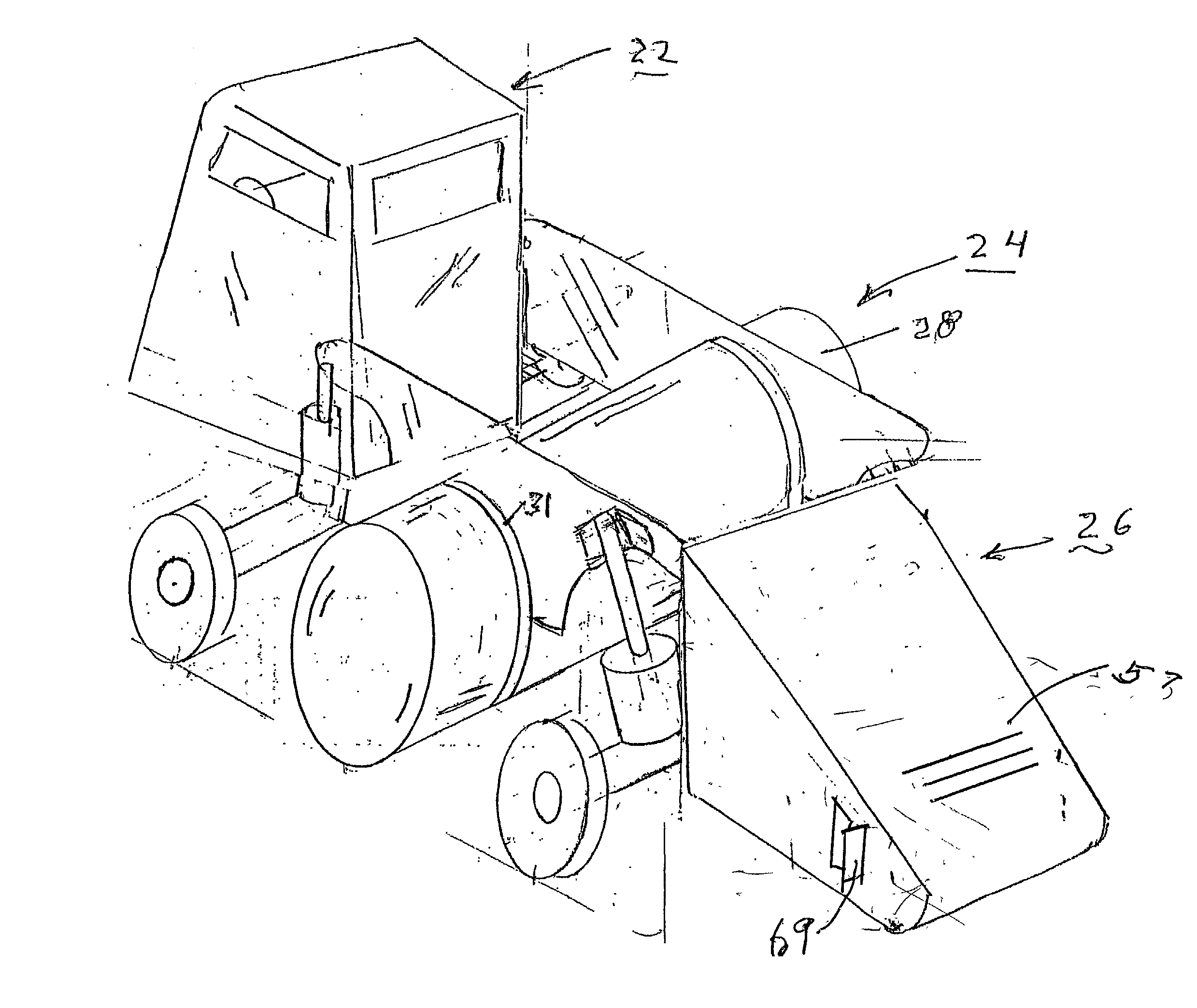
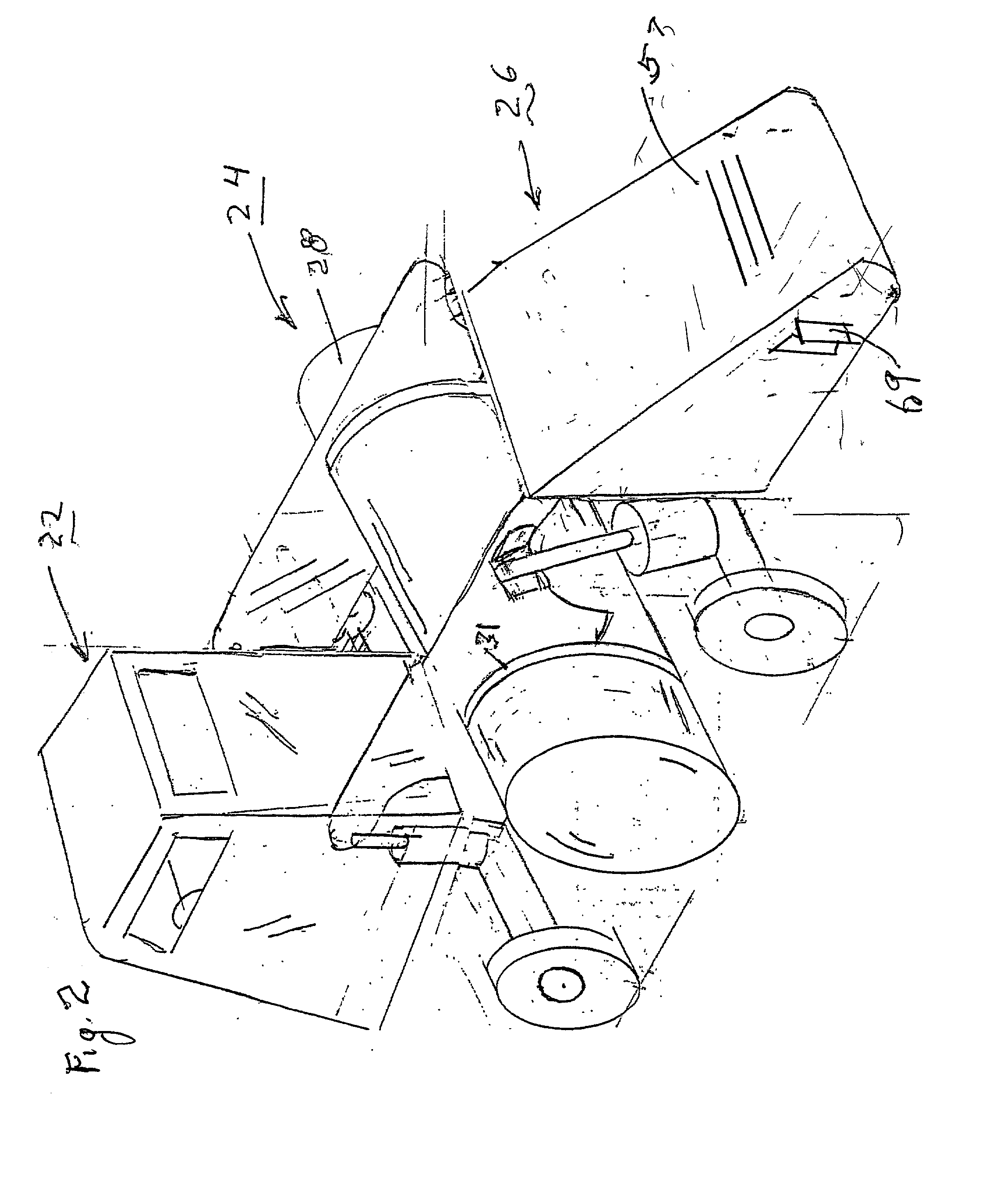
[0049] Turning now to a description of the drawings, FIG. 2 is a perspective view of the tank truck of this invention. There are shown a cab section 22, a carrier section 24 and an engine section.

[0050] One embodiment of the carrier section is presented to best advantage in FIG. 3. The carrier section includes a container and a pair of hanger members 30.

[0051] In FIG. 3, the container 28 is a cylindrical tank 28. The hanger members 30 are a pair of panels cut as yokes 30 and positioned to straddle the tank 28. One yoke 30 is close to one end of the tank opposite the other yoke 30 close to the other end of the tank 28.

[0052] As shown in FIG. 3 and to better advantage in the cutaway view of FIG. 6, the tank contains a pair of baffles 29 that are welded to the inside of the tank 28 coplanar with the yokes 30. Each baffle has openings 33 to permit free flow of the fluid inside the tank. 28.

[0053] Each yoke 30 is welded along fine 31 to the outside of tank 28.

[0054] The forward ends 32 o...


PUM


Abstract

A transport device for hauling a load having a front axle with a pair of wheels and a rear axle with a pair of wheels. Four vertical hydraulic cylinders are provided, each cylinder having a bottom end supported on one of the axles adjacent a wheel, respectively. A pair of yokes is provided. Each yoke has one end supported by the ram extending from the top of one cylinder mounted on the front axle and the other end supported by the ram extending from the top end of a cylinder on the rear axle so that the yokes are parallel to one another and extend form front to rear of the device. A container containing the load is suspended from the pair of yokes. In one version, the device is coupled for transport to a truck. In another version, an engine is mounted on a cantilever frame extending from the rear of the truck controlled by operators in a cab mounted on the front end of the device. In another version, the device has a tongue extending from the front axle and attachable to a truck tractor.

Description

[0001] This invention relates to the construction of trucks such as are used for carrying thousands of gallons of liquids and particularly to a truck in which the bed and cab of the truck are supported by a suspension system.BACKGROUND AND INFORMATION DISCLOSURE.[0002] There is a demand for trucks that are used for carrying large quantities of liquids (in excess of 4000 gal). These liquids include water such as for transporting water to the site of a fire, fuels, water, etc.[0003] The standard design approach to construction of tucks for these applications is illustrated in the assembly view of FIG. 1. There is shown a tank 10 poised for mounting on top of a "ladder" frame including beams 12 and cross members 14. The ladder frame is secured by leaf springs 16 (one for each wheel) mounted on the truck front and rear axles 20.[0004] As shown in FIG. 1, the typical tank 10 is oblong with an axis extending from the front end to the rear end of the truck bed.[0005] This conventional arra...

Claims


Application Information

Patent Timeline
Patent Type & Authority Applications(United States)
IPC IPC(8): B60P3/22
CPCB60G2300/03B60G2800/0194B60P3/2215B60G2800/914B60P3/2205B60G2800/912
Inventor COLET, RALPH
Owner COLET RALPH
Why Eureka
Try Eureka