Drain and a building structure having a drain

Inactive Publication Date: 2003-06-26
UNIDRAIN
View PDF28 Cites 37 Cited by
  • Summary
  • Abstract
  • Description
  • Claims
  • Application Information

AI Technical Summary

Benefits of technology

0032] In a preferred embodiment of the invention, the drain may further be elongated and be provided with two opposed side parts integral with the bottom part and the first part. The sidewalls extend in vertical direction from the bottom part, through and above a plane defined by the flange part. This drain is particularly suitable for use in narrowly confined spaces, such as in a shower bath where the drain extends between two opposed walls delimiting the bathroom and having each a watertight covering that covers the side walls of the drain. This allows the floor to be provided with a unidirectional slope towards the back part of the drain, making it significantly simpler to esta

Problems solved by technology

A technical problem in connection with such rooms is that the building structure defining the room must be sealed in a fluid tight manner in order to avoid water from penetrating into the wall and floor construction, which if occurring often results in rot in the structure which in turn requires a very expensive reconstruction of the structure.
While many--and excellent--solutions today exist for fluid tightening the walls and floor of such rooms no real solution to the problem regarding fluid tightening around the drain has been provided until now.
Fluid tightening around the drain is considered by experts to be a very delicate problem.
the drain cannot properly be fixed,
the drain is often misaligned during construction of the structure,
the floor is vulnerable in an area around the drain,
the floor must be provided with a four-sided slope towards the drain; however, problems with water flowing in wrong directions with generation of pools of water are often encountered in the final structure,
the joint between wall and floor close to the drain is very vulnerable with respect to leaks, as the drain does not guarantee a seal between wall and floor,
the joint between the floor and drain is vulnerable with respect to leaks,
the drain does not guarantee a sealed joint between walls and floor

Method used


Image

  • Drain and a building structure having a drain
  • Drain and a building structure having a drain
  • Drain and a building structure having a drain

Examples


Embodiment Construction

[0054] In the following the invention will be described in greater details and in particular different embodiments thereof will be addressed. The preferred embodiments will be addressed in connection with a bathroom. It should, however, be obvious for those skilled in the art, that the invention also is applicable to other kinds of rooms designed in such a manner that the walls and floor of the rooms are exposed to running water and wherein the water is to be drained.

[0055] In the following description, numerals used for identification of similar parts in different embodiments of the invention are the same in order to ease the understanding of the invention only.

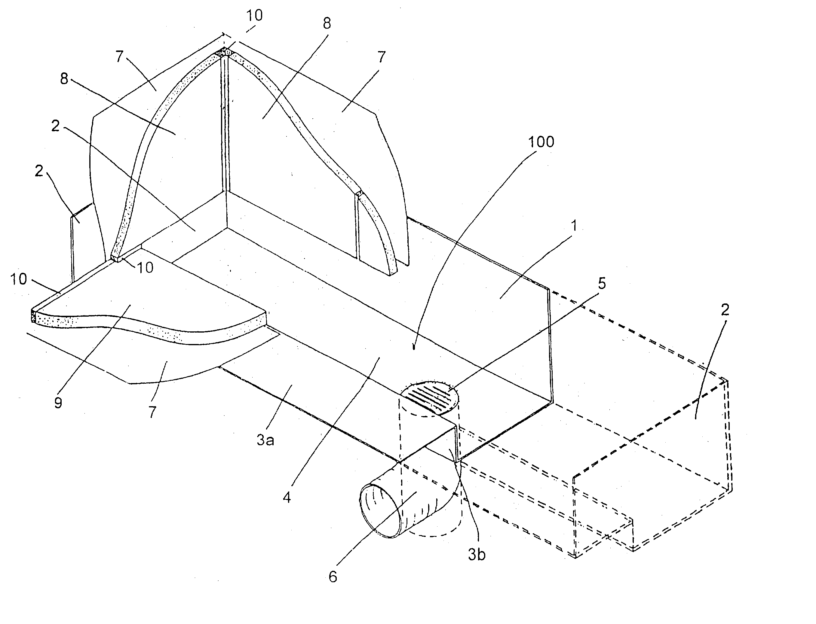
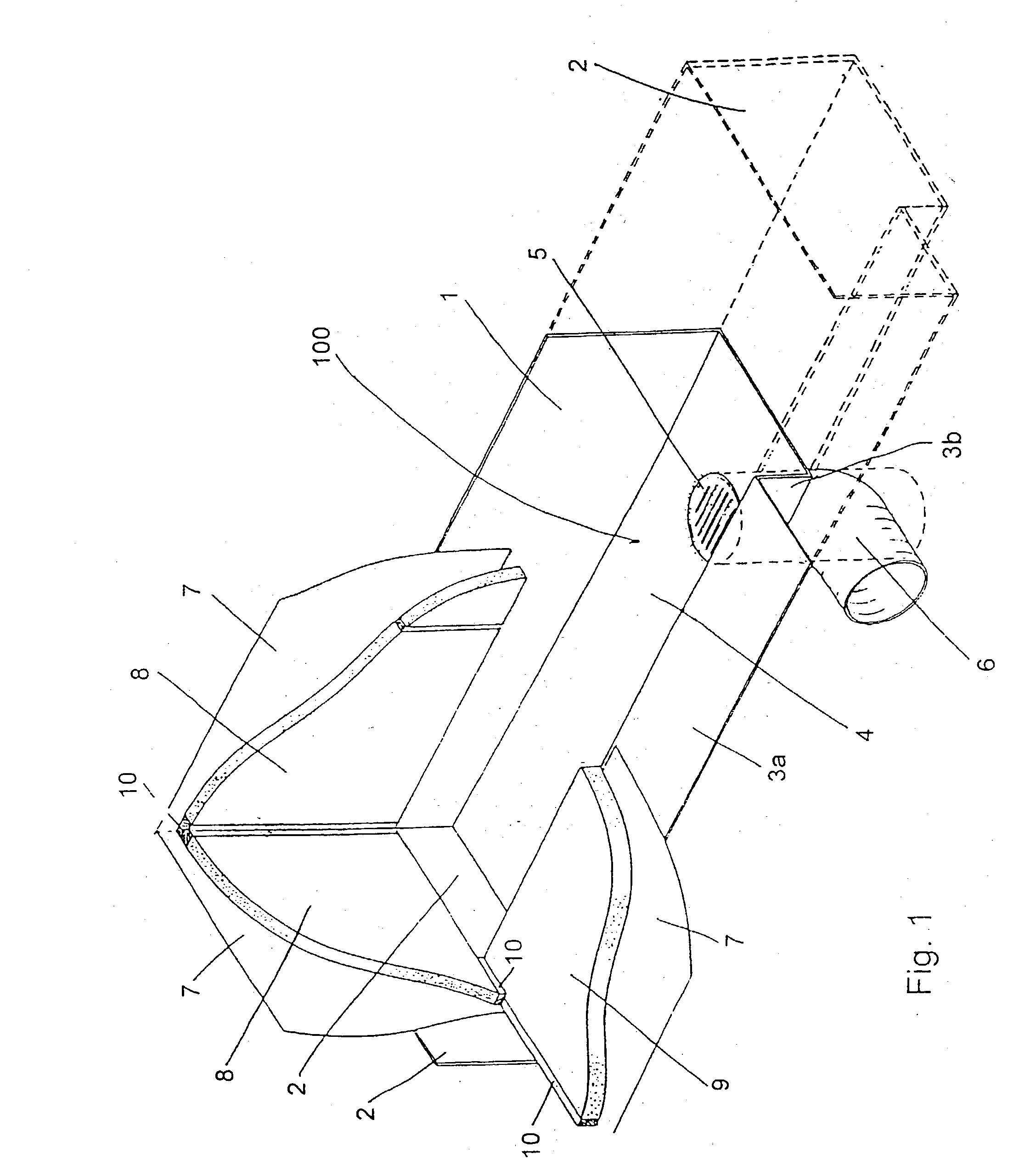
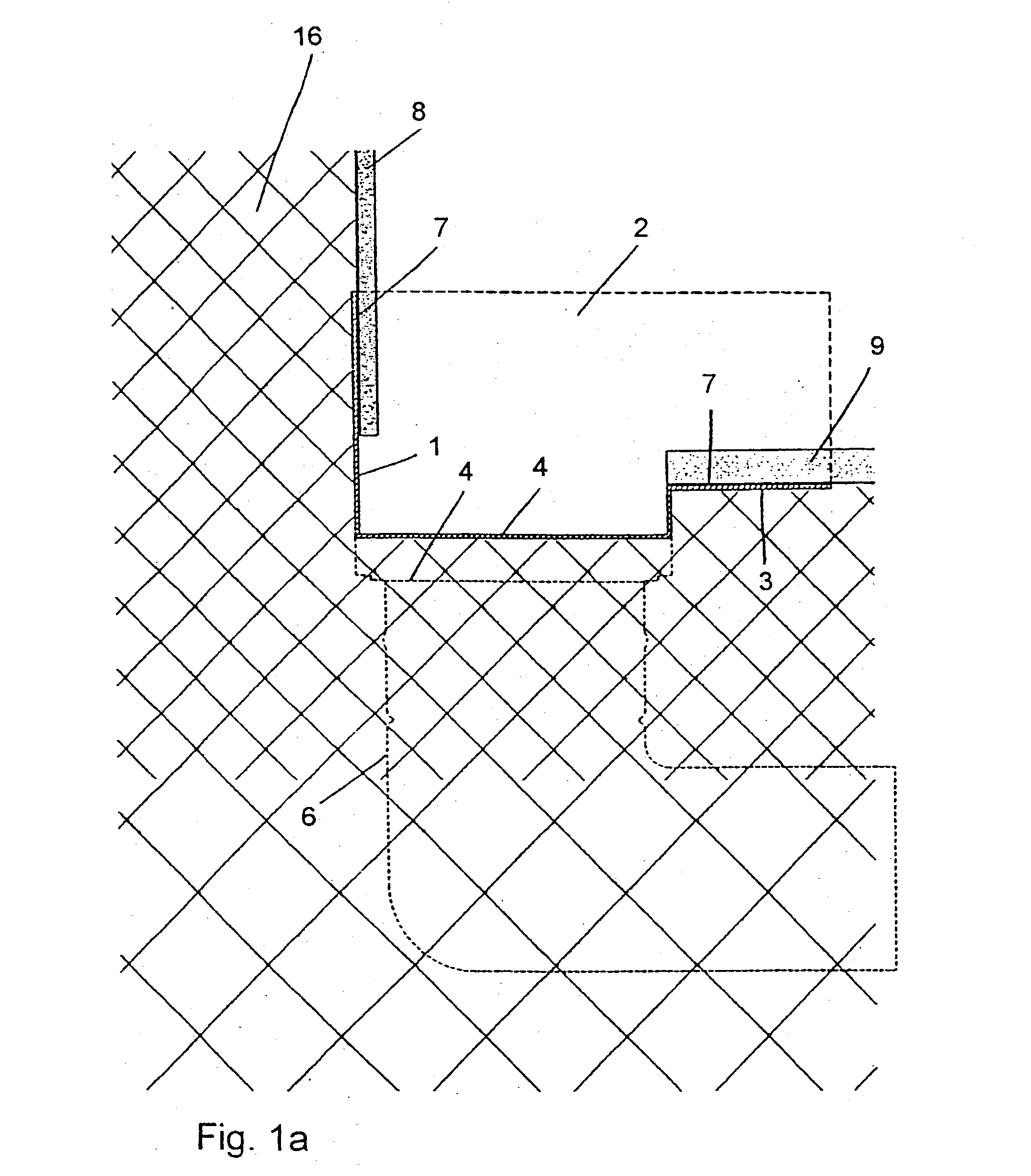
[0056] In FIG. 1 a section of the brick, concrete or plaster board wall and floor of a bathroom in which the drain is integrated is shown. The bathroom comprises the drain 100. The drain 100 is an elongated device and has a vertical back wall 1 integral with two vertical side walls 2, a front wall 3 comprising a horizontal p...


PUM


Abstract

A floor drain (100) comprising a bottom part (4) having at least one discharge opening (5), a front part being integral with the bottom part (4) and having a first part (3b) being inclined to said bottom part at an angle being at least 30°, such as at least 45°, preferably at least 60° more preferably at least 75° and even more preferably about 90° or at least 90° and having a flange part (3a) being horizontal or inclined to horizontal at an angle being less than 20° such as less than 17°, preferably less than 15°, such as less than 10°, more preferably less than 5°, tow side walls (2) integral with said bottom part and said first part, and a back part (1) being integral with said bottom part (4), said back part (1) extending vertically from the bottom part (4), through and above the plane defined by the flange part (3a).

Description

[0001] The present invention relates to a floor drain, a building structure having such a floor drain and a method for installing such a floor drain in a building structure. The building structure is in preferred embodiments of the invention a bathroom or the like in which water, being splashed to the walls and floor, is drained from the room by the drain situated in the floor and connected to the sewer.BACKGROUND FOR THE INVENTION AND INTRODUCTION TO THE INVENTION[0002] A technical problem in connection with such rooms is that the building structure defining the room must be sealed in a fluid tight manner in order to avoid water from penetrating into the wall and floor construction, which if occurring often results in rot in the structure which in turn requires a very expensive reconstruction of the structure.[0003] While many--and excellent--solutions today exist for fluid tightening the walls and floor of such rooms no real solution to the problem regarding fluid tightening aroun...

Claims


Application Information

Patent Timeline
IPC IPC(8): E03F5/04E03C1/12
CPCE03F5/0406E03F2005/0418E03F5/0408E03F5/0407Y02A30/60
Inventor NIELSEN, CLAUS DYRE
Owner UNIDRAIN
Why Eureka
Try Eureka