Inductive component and method for the production thereof

a technology of inductive components and components, applied in the field of inductive components, can solve problems such as complete failure of inductive components

Inactive Publication Date: 2003-06-26
ROBERT BOSCH GMBH
View PDF2 Cites 5 Cited by
  • Summary
  • Abstract
  • Description
  • Claims
  • Application Information

AI Technical Summary

Problems solved by technology

Since temperature changes thus constantly subject the coil wire to alternating mechanical stress, in an extreme case a fatigue rupture can ensue in the region between the conductor rail and the coil, or the coil-wire-conductor rail arrangement, which can lead to the complete failure of the inductive component.

Method used


Image

  • Inductive component and method for the production thereof
  • Inductive component and method for the production thereof
  • Inductive component and method for the production thereof

Examples


Embodiment Construction

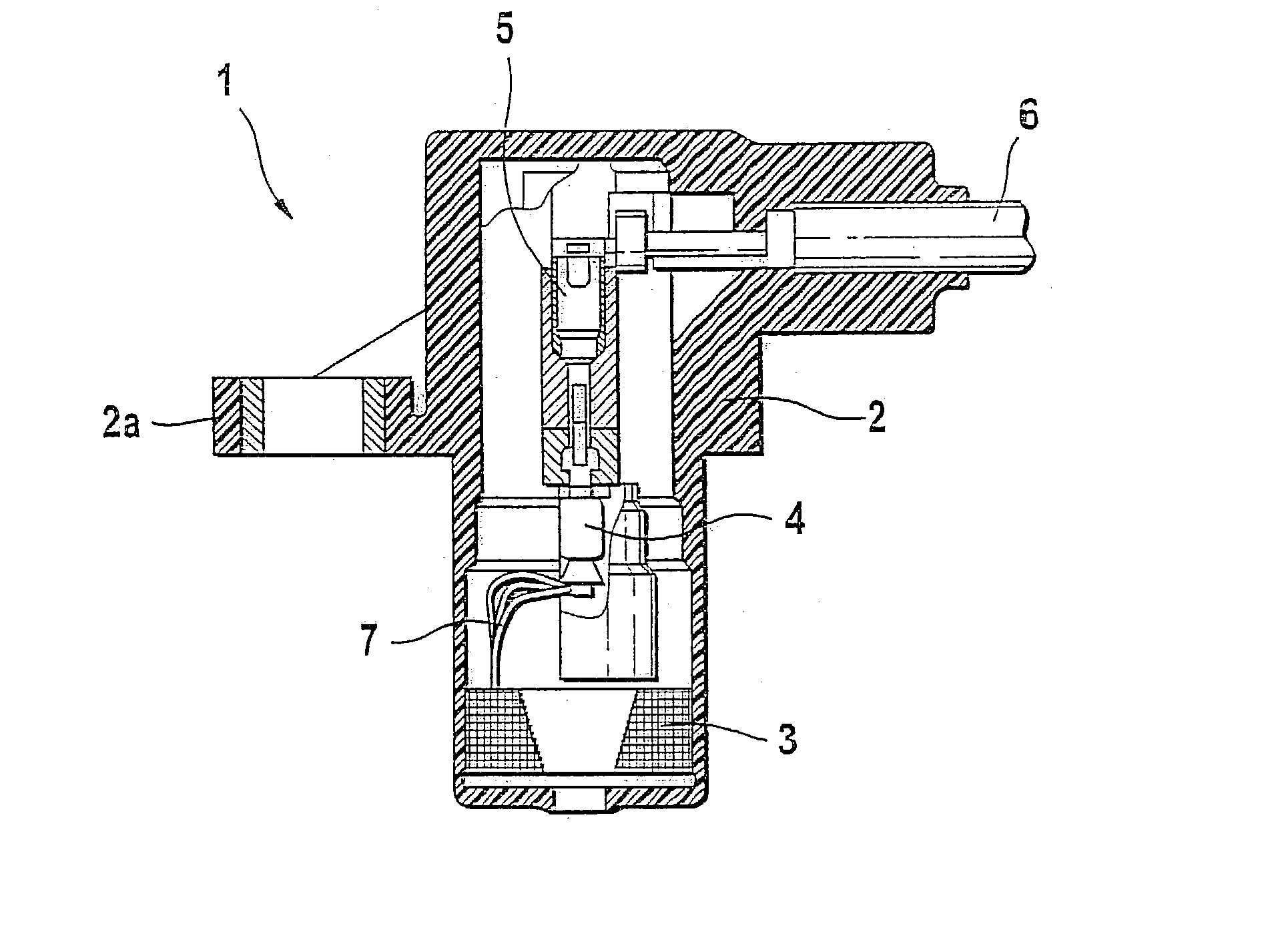
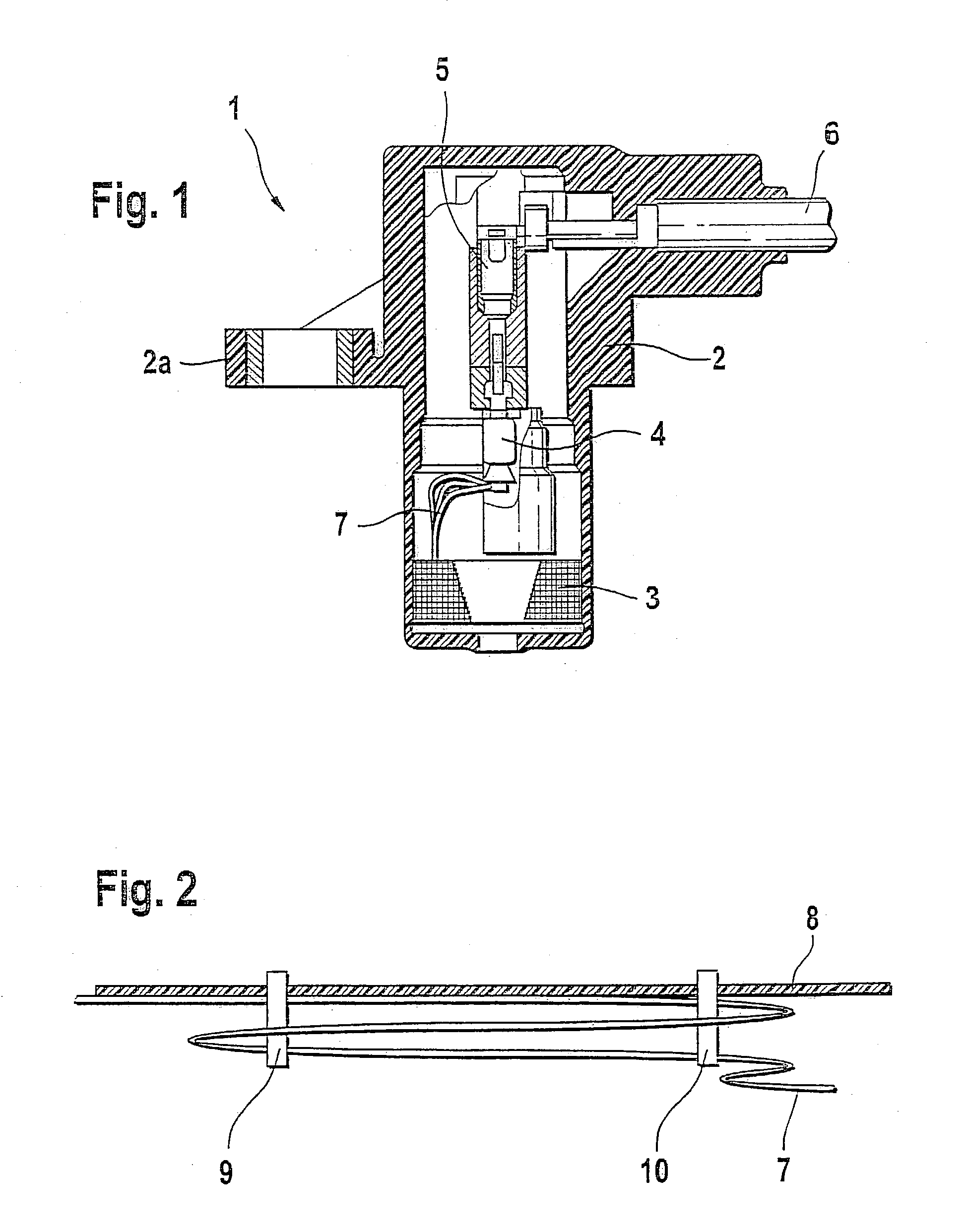
[0015] In FIG. 1, an rpm sensor 1 is shown, which has a housing 2 produced by injection molding. A coil 3 is located in the housing 2, and two conductor rails 4 are connected to it, only one of which is visible in FIG. 1. The ends of the conductor rails 4 are connected to a contact array 5, to which a cable 6 leading to the outside can be connected. For mechanically fastening the rpm sensor 1 to a vehicle housing, for instance, a flangelike extension 2a is embedded on the housing 2.

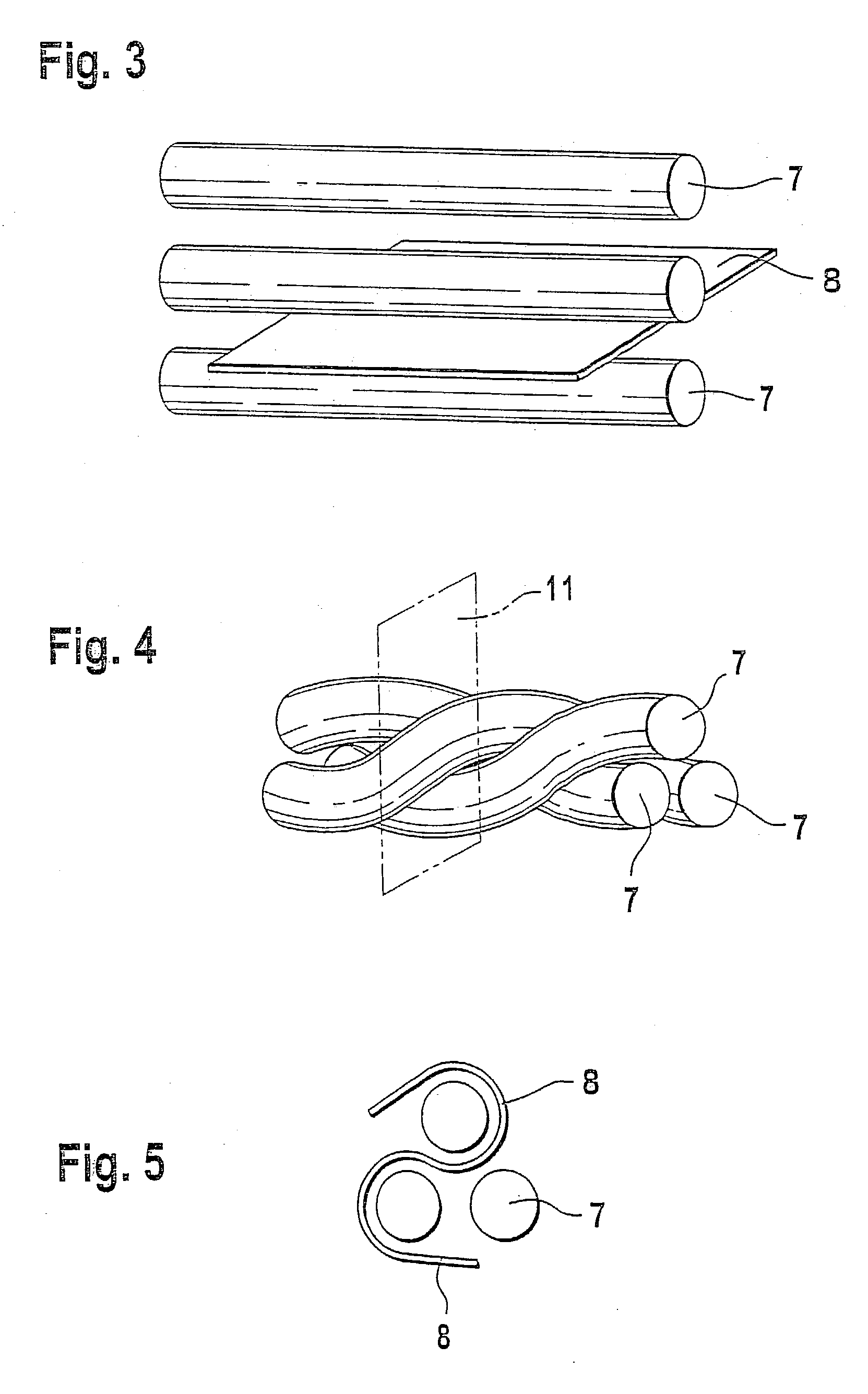
[0016] The ends of the conductor rails 4 that are located toward the coil are designed such that secure contacting of the connection wires 7 of the coil 3 can be performed here. The embodiment of these connection wires 7 is shown only schematically in FIG. 1. The design, according to the invention, of the connection wires 7 in the twisted composite structure with a film will now be explained in conjunction with the other drawings. Toward the bottom, that is, toward a gear wheel, not shown, or other body o...


PUM

PropertyMeasurementUnit
magnetic fieldaaaaaaaaaa
temperatureaaaaaaaaaa
elasticaaaaaaaaaa

Abstract

The invention relates to an inductive component, having a coil (3) disposed in an injection molded housing (2) and having conductor rails (4), also mounted in the housing (2), to each of which the ends of the coil wires are contacted in the form of connection wires (7). Each of the connection wires (7) between the coil (3) and the respective conductor rail (4) forms one composite structure, comprising windings and twists, with a film (8) located between and/or outside them. The injection molding compound of the housing (2) can be applied directly to these composite structures. Preferably, the composite structure comprises at least two windings, which are twisted together and are disposed in the direction of the course of the connection wires (7).

Description

PRIOR ART[0001] The invention relates to an inductive component, in particular an inductive sensor, as generically defined by the preambles to the main claim and the method claim.[0002] From European Patent Disclosure EP 0 632 897 B1, an inductive rpm sensor is known in which an electrical coil is disposed in a housing in such a way that a change in magnetic field, for instance, can be detected by a rotating part in the region of a pole pin of the coil core, and an rpm sensor can thus be constructed. This rpm sensor, in the area of interest here, comprises a conductor rail, the connection wire of the coil, and the coil itself. It is usual here that to sheathe this region, an injection molding compound is sprayed directly onto the region of the conductor rail, on which the ends of the windings of the coil [verb missing].[0003] Because of the different coefficients of expansion between the injection molding compound and the connection wire, the latter as a rule being of copper, a rela...

Claims


Application Information

Patent Timeline
Patent Type & Authority Applications(United States)
IPC IPC(8): G01D5/20G01D11/24G01P1/02G01P3/488
CPCG01D5/2013G01P1/026G01D11/245H01F41/02
Inventor KLENK, MATHIAS
Owner ROBERT BOSCH GMBH
Why Eureka
Try Eureka