Fuel injection valve and a method for operating the same

a technology of fuel injection valve and fuel injection pump, which is applied in the direction of fuel injection pump, valve operating means/release devices, machines/engines, etc., can solve the problems of difficult design of appropriate control elements, small improvement, and high cost of manufacturing an arrangemen

Inactive Publication Date: 2003-07-10
ROBERT BOSCH GMBH
View PDF7 Cites 35 Cited by
  • Summary
  • Abstract
  • Description
  • Claims
  • Application Information

AI Technical Summary

Problems solved by technology

Designing appropriate control elements is difficult and also yields only slight improvements in the closing times.
One disadvantage in the fuel injector known from German Patent 23 06 007 C3 is that it is very expensive to manufacture an arrangement that has three circuits, which drive the three windings of the solenoid coil.
This places stress on the electrical components.

Method used


Image

  • Fuel injection valve and a method for operating the same
  • Fuel injection valve and a method for operating the same
  • Fuel injection valve and a method for operating the same

Examples


Embodiment Construction

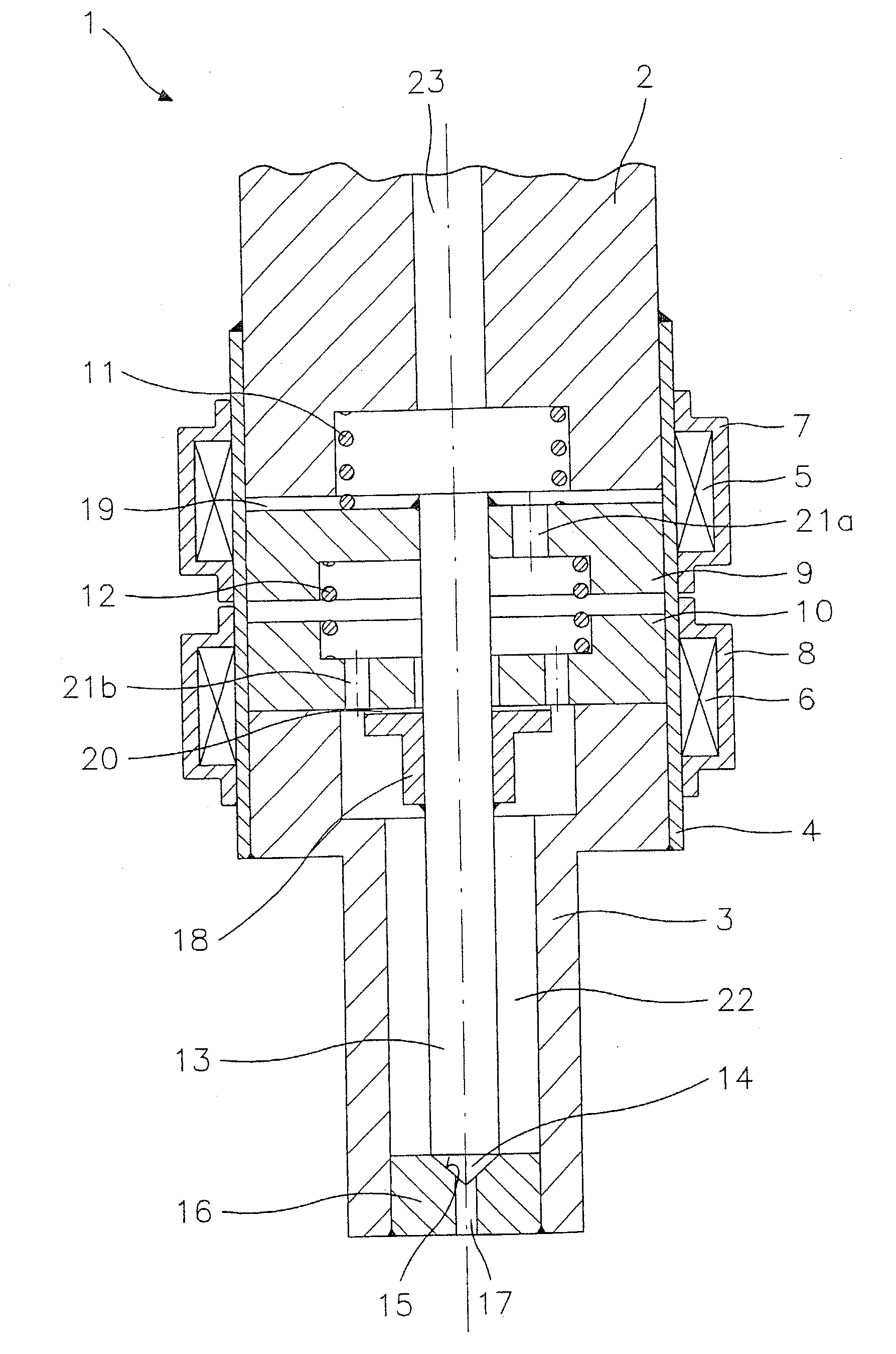
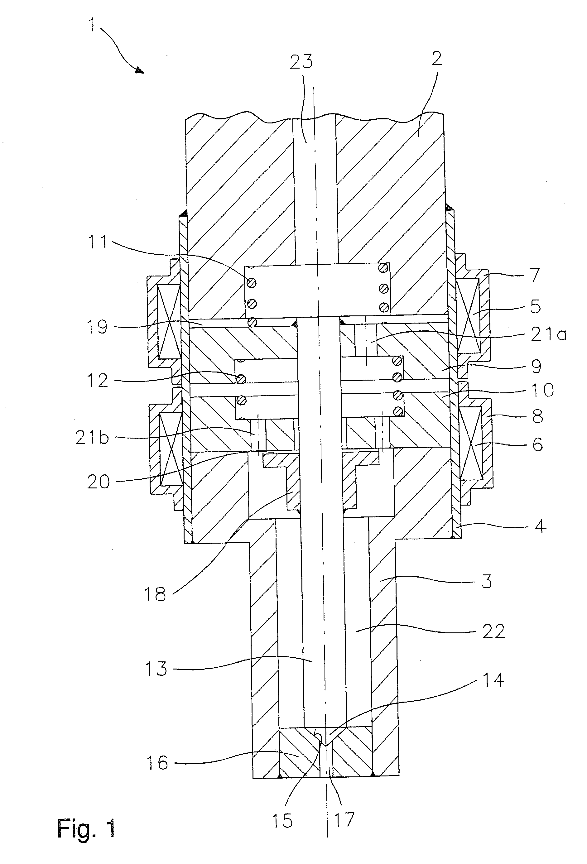
[0017] FIG. 1 in a partial cutaway representation shows the spray-discharge-side part of a fuel injector 1. Fuel injector 1 is particularly well suited for the direct injection of fuel into a combustion chamber, not depicted further, of a mixture-compressing, spark-ignition internal combustion engine.

[0018] Fuel injector 1 includes a core 2 and a nozzle body 3, which are surrounded by a valve housing 4. A first solenoid coil 5 and a second solenoid coil 6 are arranged on valve housing 4 and are surrounded by a first magnetic backflow body 7 and a second magnetic backflow body 8, respectively. Arranged between core 2 and nozzle body 3 are a first armature 9 and a second armature 10, which cooperate with solenoid coils 5 and 6. First armature 9 is acted upon in the closing direction by a first resetting spring 11, whereas second armature 10, in the idle state of fuel injector 1, rests on nozzle body 3. Clamped between first armature 9 and second armature 10 is a second resetting sprin...


PUM


Abstract

A fuel injector (1), especially an injector for fuel injection systems of internal combustion engines, includes a first solenoid coil (5), which cooperates with the first armature (9), a valve needle (13) in a force-locking connection with the first armature (9) for actuating a valve-closure member (14), which together with a valve seat surface (15) forms a sealing seat, and a second solenoid coil (6). In this context, the first armature (9) is acted upon in a closing direction by a first resetting spring (11). A second armature (10) cooperates with the second solenoid coil (6) such that, when the first solenoid coil (5) and the second solenoid coil (6) are supplied with current, a limit stop body (18) that is connected with the valve needle (13) strikes against the second armature (10).

Description

BACKGROUND INFORMATION[0001] The present invention relates to a fuel injector according to the species of claim 1, and to a method according to the species of claim 9, for the actuation of a fuel injector.[0002] The closing times of fuel injectors are lengthened, on the one hand, by the adhesion forces between the armature and the core and, on the other hand, by eddy currents. To decrease the delay, it is known to cause a current to flow through the solenoid coil in the reverse direction in response to ending the current pulse that excites the fuel injector, in order to accelerate the decay of the residual field. Designing appropriate control elements is difficult and also yields only slight improvements in the closing times.[0003] Another possibility is seen in building up one magnetic field for opening the fuel injector and building up a second magnetic field to hold the fuel injector in its open position. The strength of the holding field can then be selected so as to be so small...

Claims


Application Information

Patent Timeline
Patent Type & Authority Applications(United States)
IPC IPC(8): F02B75/12F02M45/08F02M45/12F02M51/00F02M51/06F02M61/16F02M61/20F02M63/00
CPCF02B2075/125F02M45/083F02M45/12Y02T10/123F02M51/0671F02M61/161F02M61/205F02M51/0617Y02T10/12F02M51/06
Inventor HOHL, GUENTHER
Owner ROBERT BOSCH GMBH
Why Eureka
Try Eureka