[0004] The injection nozzle according to the present invention, with the characterizing features of the independent claim, has the
advantage over the prior art that both the first nozzle needle and the second nozzle needle are controlled directly as a function of the
injection pressure. The injection nozzle according to the present invention thus eliminates the costs of implementing a
servo control. Moreover, the injection nozzle according to present invention has comparatively high closing dynamics for both nozzle needles and also has high opening dynamics for the second nozzle needle at comparatively high injection pressures. As a result, the nozzle needles react very quickly to the closing so that extremely short closing times can be achieved. The second nozzle needle then also reacts to the opening with a corresponding
rapidity so that relatively short opening times for the second nozzle needle can also be achieved.
[0005] Thanks to the proposed throttled
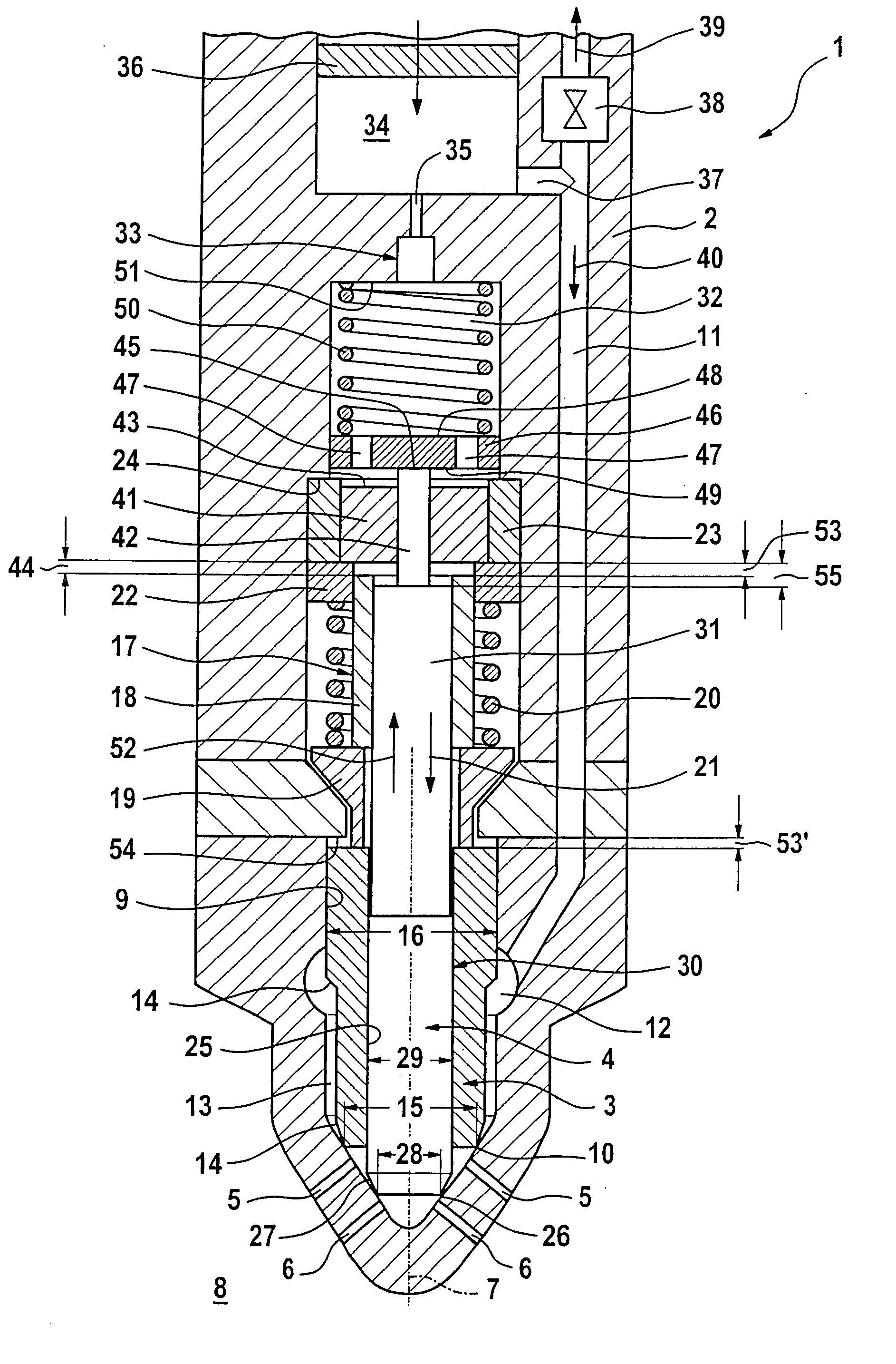
coupling of the control chamber to the pressure chamber, a pressure compensation between the pressure chamber and the control chamber only occurs in a delayed fashion. In order to open the nozzle needles, the pressure in the pressure chamber, namely the
injection pressure, is increased in order to act directly on a corresponding pressure shoulder of the first nozzle needle. With sufficient injection pressure, the first nozzle needle opens. When the first nozzle needle is opened, the injection pressure can also build up against a corresponding pressure shoulder of the second nozzle needle. Since the pressure in the control chamber rises significantly more slowly, the second nozzle needle is thus already able to open at low injection pressures, i.e. earlier. In the closing of the nozzle needles, the delayed pressure compensation between the control chamber and the pressure chamber results in a shortening of the closing times. In order to close the nozzle needles, the injection pressure in the pressure chamber is reduced. This reduces the pressure acting on the pressure shoulders of the nozzle needles in the opening direction. The pressure in the control chamber cannot fall as quickly, thus resulting in very powerful closing forces for the nozzle needles, which forces accelerate, i.e. shorten, the closing process of the two nozzle needles. The essential thing here is that an additional
servo valve is not required for triggering the second nozzle needle to open and close.
[0006] According to an advantageous embodiment form, a first closing spring can be provided, which, on the one hand, drives the first nozzle needle or first needle unit in the closing direction and on the other hand, directly or indirectly drives the first control piston into an initial position in which there is an axial play between the first control piston and the first nozzle needle or first needle unit. Because of this design, there is an axial play between the first control piston and the first nozzle needle or first needle unit when the first nozzle needle is in its closed position. When the first nozzle needle opens, it can lift independently of the first control piston within the range of the axial play, as a result of which the first nozzle needle is decoupled from the forces acting on the first control piston in the control chamber.
[0007] According to a preferred modification, the first control piston can constitute a first
stroke stop for the first nozzle needle or first needle unit in such a way that in an open position of the first nozzle needle, the first control piston comes into direct axial contact with this first nozzle needle or the first needle unit. For the closing process, this means that the first control piston can transmit the compressive force prevailing in the control chamber directly to the first nozzle needle or first needle unit, in particular without an idle
stroke. On the one hand, this achieves a rapid reaction of the first nozzle needle and on the other hand, makes it possible to avoid generating
noise.
[0008] In another advantageous modification, the first control piston can constitute a second
stroke stop for the second nozzle needle or second needle unit in such a way that in an open position of the second nozzle needle, the first control piston comes into axial contact directly against this second nozzle needle or second needle unit. On the one hand, this embodiment form also lends the first control piston a double function and on the other hand, it assures a rapid reaction of the second nozzle needle during closing; here, too, it is possible to avoid an idle stroke and a consequent generation of
noise.

