Air flow sensing and control for animal confinement system

a technology of air flow sensing and control, which is applied in the direction of pressure difference measurement between multiple valves, digital computer details, instruments, etc., can solve the problems of not having the capability to monitor and maintain the desired air flow within the cage and rack or otherwise monitor and control the environment in the cage and rack, and the current rack and cage ventilation system cannot provide rack and/or cage-level control of the environment in the rack and/or cag

Inactive Publication Date: 2003-07-10
COHEN ADAM +1
View PDF2 Cites 30 Cited by
  • Summary
  • Abstract
  • Description
  • Claims
  • Application Information

AI Technical Summary

Problems solved by technology

Although the related ventilated cage and rack systems put the cages under positive pressure to create air flow through the cage, those systems do not have the capability to monitor and maintain the desired air flow within the cage and rack or to otherwise monitor and control the environment i

Method used


Image

  • Air flow sensing and control for animal confinement system
  • Air flow sensing and control for animal confinement system
  • Air flow sensing and control for animal confinement system

Examples


Embodiment Construction

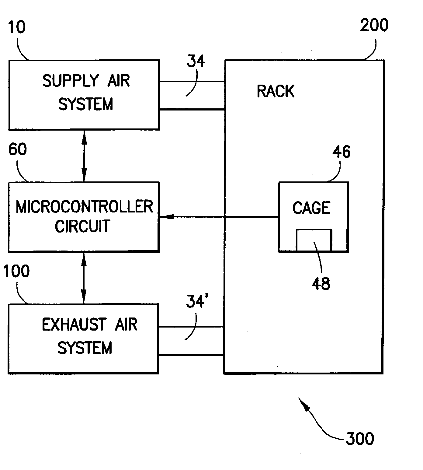
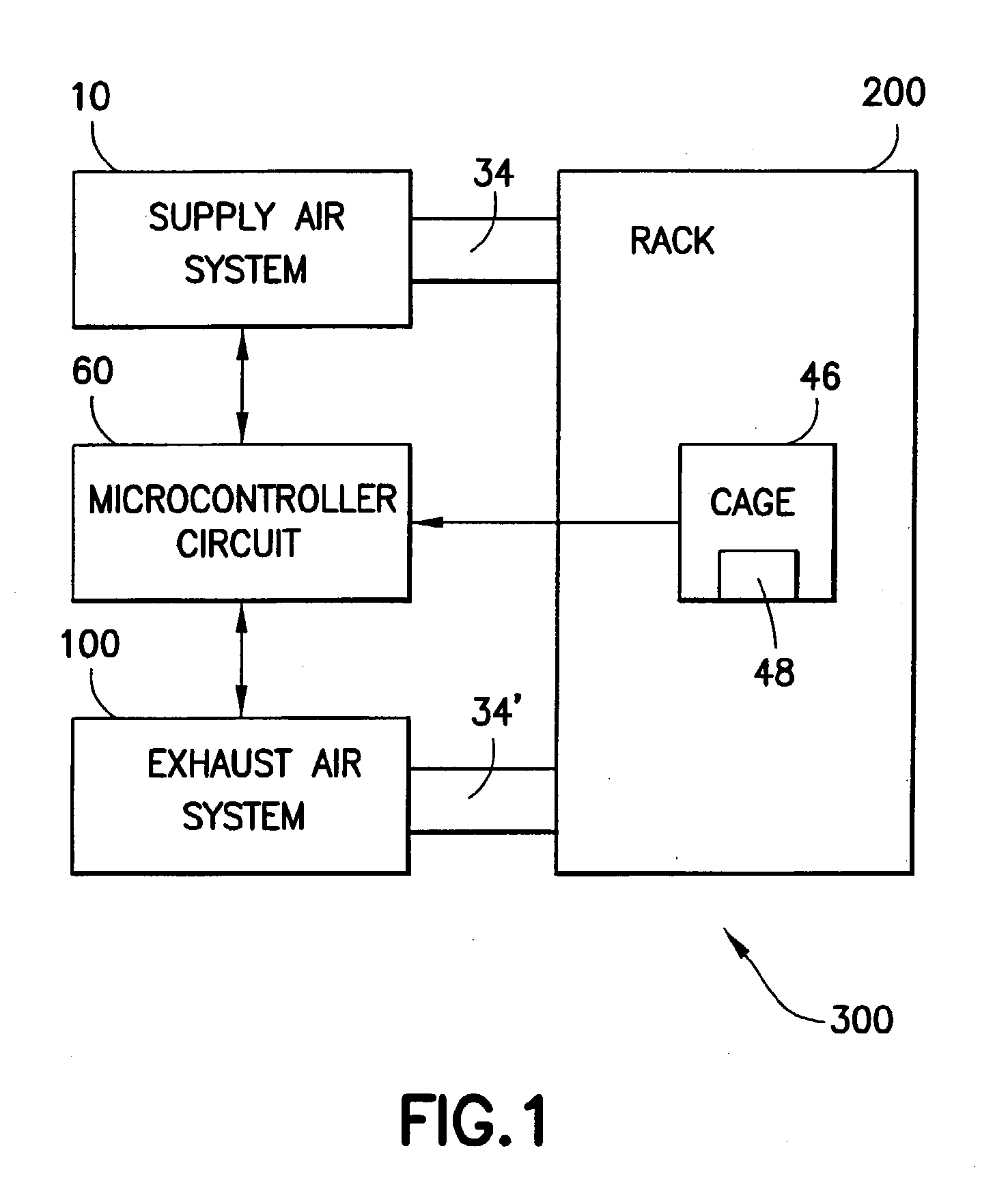
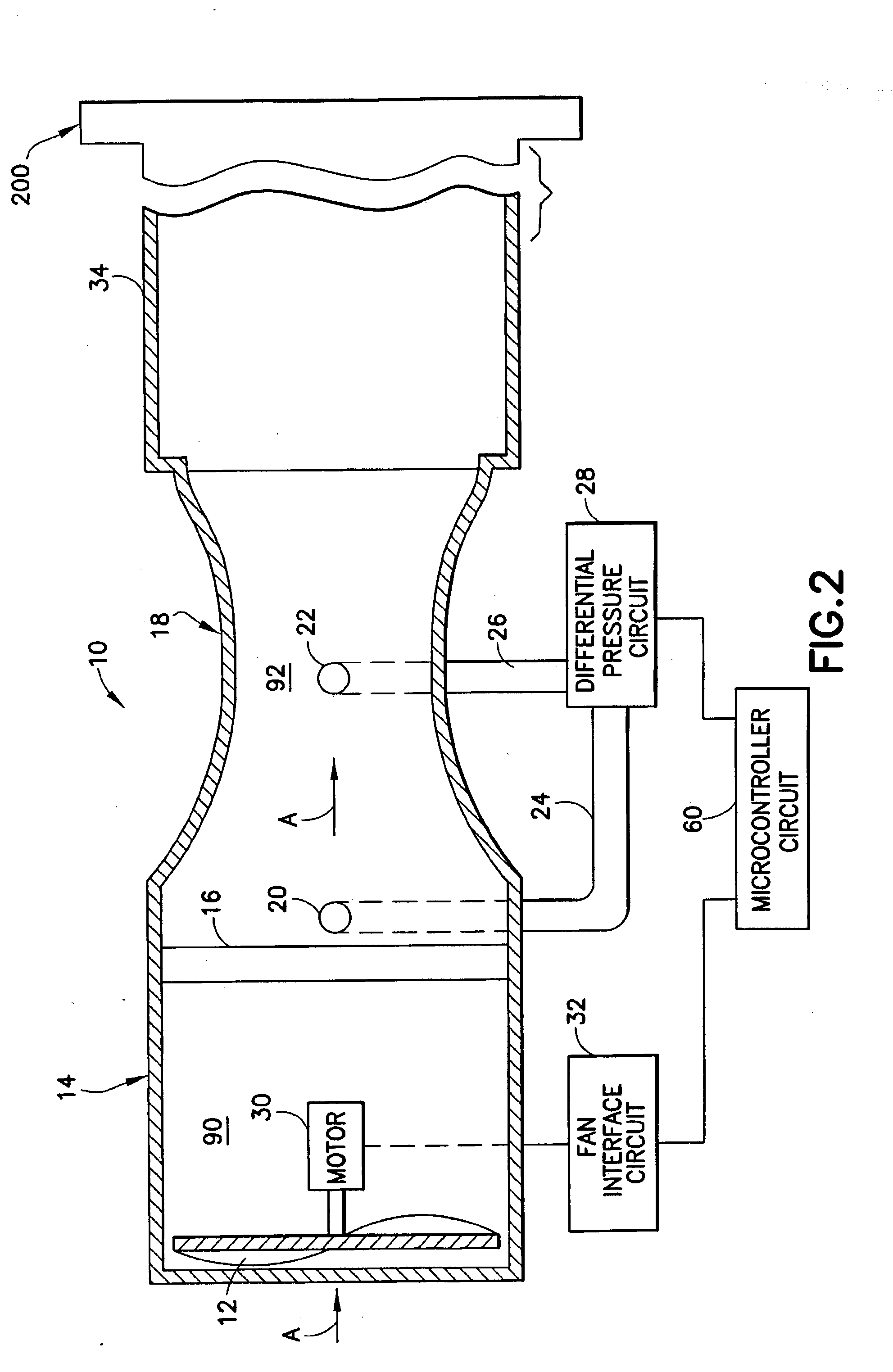
[0027] The present invention is directed to an environmental monitoring and controlling system for a ventilated cage and rack system. The present invention monitors and measures air flow in the rack at either the rack or cage level. At the rack level, pressure in a supply air system is measured at two pressure points to accurately monitor the air flow rate into the rack. In addition, pressure may be measured at two pressure points in an exhaust air system to accurately monitor the air flow rate out of the rack. At the cage level, a cage may be equipped with a highly accurate flow sensor, consisting of a Venturi tube and thermistor, (since an extremely low pressure differential (.about.0.1" H2O) is used to force air into each cage, the device to measure the flow cannot introduce significant air impedance. Thus, in an embodiment of the invention, a Venturi tube in conjunction with a porous material is used to condition the flow where an extremely small hot anemometer element (0.016" d...


PUM


Abstract

A system for monitoring the environment in a rack having a plurality of cages for housing a plurality of laboratory animals, the rack receiving an input air flow from an external air supply unit through an input conduit, and exhausting an air flow output from an output conduit. The system may comprise a supply air system coupled to the input conduit for monitoring the input air flow to the rack in an input air flow direction. The supply air system may comprise a flow tube, through which the air flows, an air flow sensor located within the flow tube for determining the air flow rate taken at a location along the input air flow direction, and for providing an indication of the flow rate, an air flow stabilizer located within the flow tube at a location upstream from the flow sensor, for stabilizing the air flowing to the air flow sensor, and a microcontroller for receiving the indication of the determined air flow rate from the air flow sensor and for monitoring the air flow to the rack. Similarly, an exhaust air system coupled to the output conduit for monitoring the output air flow from the rack in an output air flow direction may be used instead of, or in conjunction with the supply air system. Further, the system may be implemented at either the rack or cage monitoring and/or control levels.

Description

[0001] This Application is a CIP of a U.S. patent application, filed on Oct. 8, 2002, entitled Improvements In Air Flow Sensing and Control For Animal Confinement System, which was a CIP of U.S. patent application Ser. No. 09 / 706,516, filed Nov. 6, 2000, which claimed the benefit of U.S. Provisional Patent Application No. 60 / 164,028, filed on Nov. 5, 1999. This Application also claims the benefit of U.S. Provisional Patent Application No. 60 / 349,622, filed Oct. 19, 2001, and a U.S. Provisional Patent Application No. 60 / 403,943, entitled Improvements In Air Flow Sensing And Control For Animal Confinement System, filed on Aug. 16, 2002. The contents of these applications are incorporated herein by reference.[0002] 1. Field of the Invention[0003] The present invention is directed to rack-level and cage-level environmental monitoring and control in ventilated cage and rack systems.[0004] 2. Description of Related Art[0005] It is well-known in the art to house laboratory animals, such as...

Claims


Application Information

Patent Timeline
IPC IPC(8): A01K1/03G01F1/68G01F5/00
CPCA01K1/031G01F5/00G01F1/68G01F1/44
Inventor COHEN, ADAMTANG, JOSH
Owner COHEN ADAM
Why Eureka
Try Eureka