Printed circuit board-based current sensor

a current sensor and printed circuit board technology, applied in the direction of instruments, measurement devices, basic electric elements, etc., can solve the problems of high space requirement, high cost of manufacturing the device as a whole, and numerous different steps of production

Inactive Publication Date: 2003-07-24
PHOENIX CONTACT GMBH & CO KG
View PDF0 Cites 66 Cited by
  • Summary
  • Abstract
  • Description
  • Claims
  • Application Information

AI Technical Summary

Benefits of technology

[0005] The device according to the invention for a current acquisition coil is realized with the help of a printed circuit board, which can be flipped open in such a way that the current-carrying conductor to be measured can also be inserted in the provided area of the coil without interrupting or deactivating the current-carrying conductor. The opened device for a current acquisition coil is closed for measurement in such a way that the current-carrying conductor is completely enclosed by the current acquisition coil, and the current acquisition coil can measure the current of the current-carrying conductor according to the Rogowski principle. To satisfy additional requirements on the current acquisition coil relating to symmetrical structure or compactness, a multi-layer printed circuit board must be used. This offers more ways in which to control the printed conductor, and enables the most symmetrical structure possible for the current acquisition coil winding.
[0006] The printed circuit board of the device for measuring AC currents is dimensioned in such a way that additional electronic components of an evaluation unit can be arranged thereupon. Relative to prior art, this makes it possible as a whole to dimension on a smaller scale and more cost effectively. The evaluation unit can here perform a measured value conversion for conditioning measured value signals for open-loop and closed-loop controllers, running comparisons with limiting values and generating "too-low" or "too-high" messages, or for other applications.
[0007] The multi-layer printed circuit board structure results in a symmetrical design for the individual windings. In this case, the windings of the coil segment for the first winding direction are arranged on two layers for the printed conductors provided exclusively for this coil segment. With respect to the windings of the coil segment for the second winding direction, e.g., return direction, there are two layers of printed conductors provided exclusively for this coil segment. This makes more free space available for the geometric configuration of the printed conductors.

Problems solved by technology

However, the disadvantage to this design is that production requires numerous different steps.
Another disadvantage is that, when setting up a current sensor with an integrated electronic evaluation or calculation circuit, the coil in the form described in DE 195 05 812 C2 as a component in addition to the electronic components of the evaluation or calculation circuit have to be placed, secured and electrically connected.
Therefore, the integration of this coil into an electronic evaluation or corrective calculation circuit is associated with a high space requirement and high costs for manufacturing the device as a whole.
The key disadvantage to the design described in U.S. Pat. No. 5,414,400 is that the current-carrying conductor must also be routed through the borehole enveloped by the coil.
As a result, a current acquisition coil given this design cannot be placed around a current-carrying conductor for purposes of current acquisition at a later time.
Another disadvantage is that the coil as designed has a go-and-return type of winding.
This disadvantages stems from the geometric requirement that the windings for practically two coils lying one inside the other be flatly accommodated on a printed circuit board.

Method used


Image

  • Printed circuit board-based current sensor
  • Printed circuit board-based current sensor
  • Printed circuit board-based current sensor

Examples


Embodiment Construction

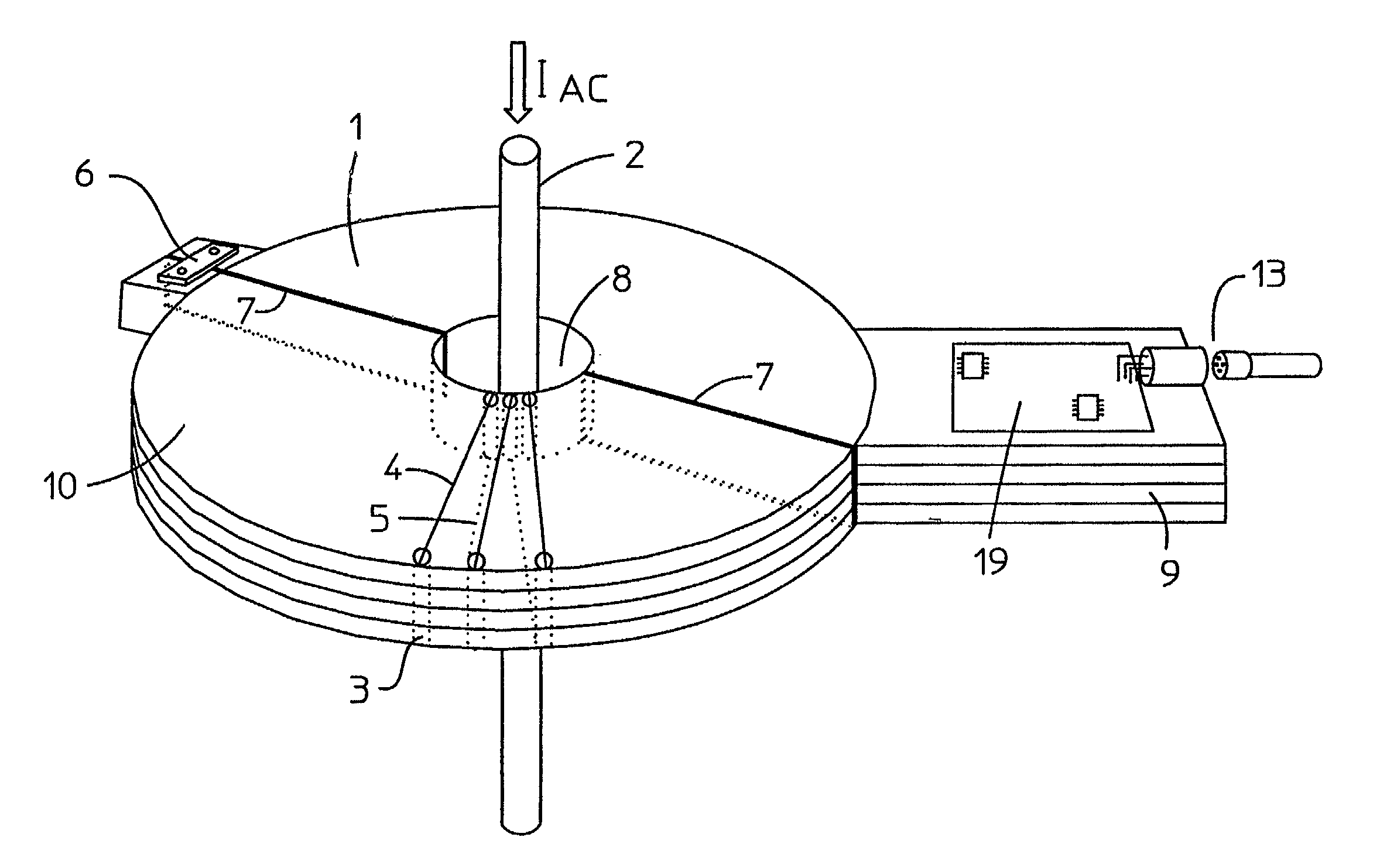
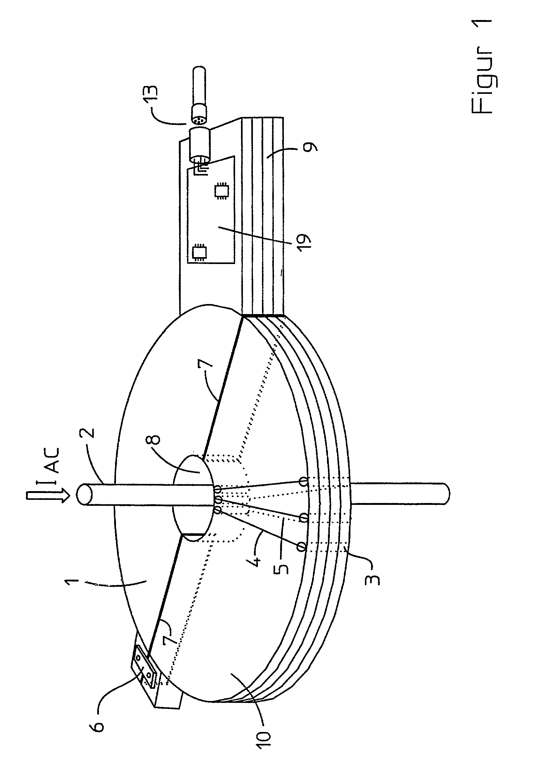
[0014] FIG. 1 shows the arrangement according to the invention of a current sensor with a flip-open, annular printed circuit board as the current acquisition coil. The hinge 6 provides a flip-open link between the one printed circuit board half 1 and the second printed circuit board half 10. The current-carrying conductor 2 with its current to be measured is axially oriented and routed through the middle of the current acquisition coil. The printed conductors of the individual layers are not shown, but alluded to with 4 and 5. The additional part of the printed circuit board 9 is preferably used to hold electric or electronic components for an evaluation circuit 19, which issues a scaled measuring signal to the output 13.

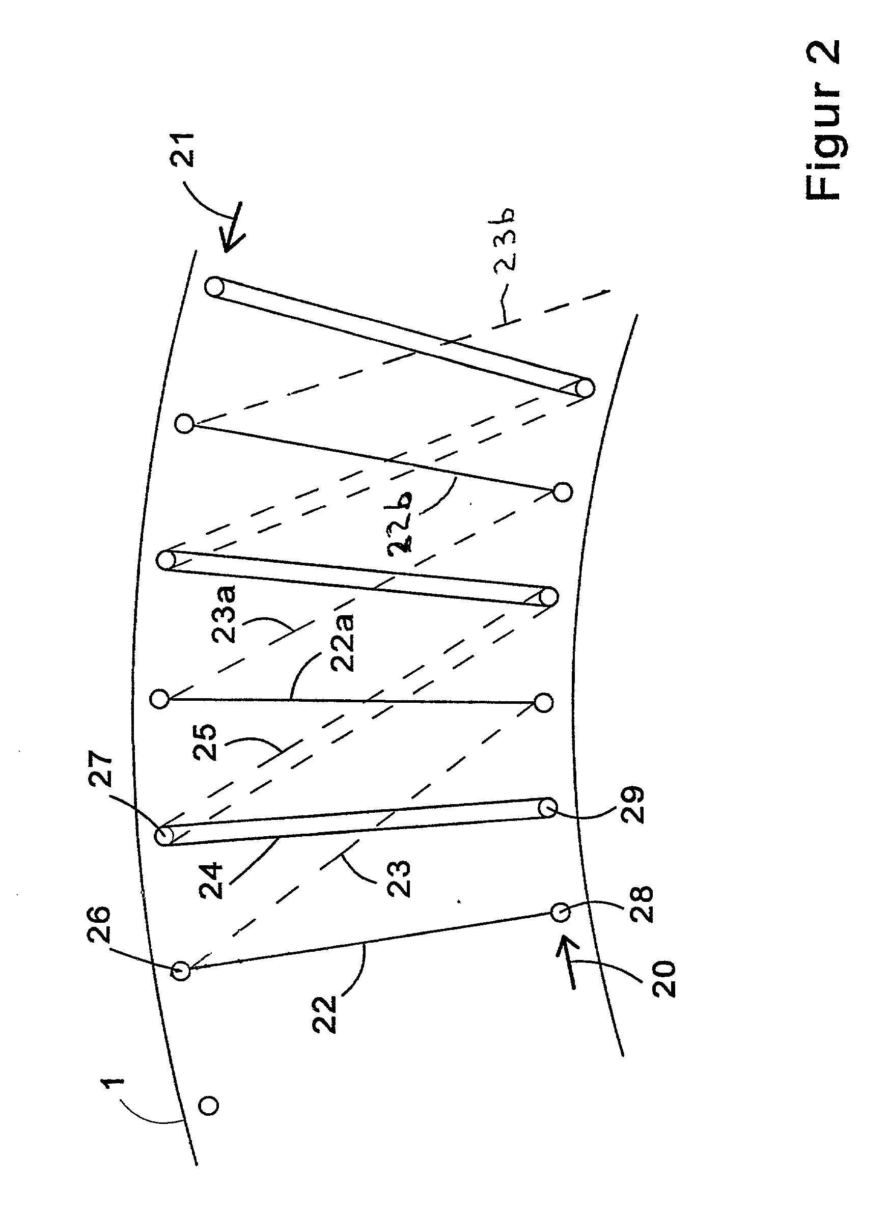
[0015] FIG. 2 shows the arrangement of printed conductors for generating a current acquisition coil. In this case, the printed conductors 22, 22a, 22b of the winding and the corresponding additional printed conductors on the top of the incoming coil winding 20 are o...


PUM

PropertyMeasurementUnit
flexibleaaaaaaaaaa
structureaaaaaaaaaa
AC currentsaaaaaaaaaa

Abstract

The object of the invention is to provide a slotted current acquisition coil according to the Rogowski principle in which the printed circuit board base of the measuring coil can be opened to insert an electrical conductor to be measured without having to interrupt the latter. To this end, the two printed circuit board segments linked together by a hinge are opened. Twisting a single-piece printed circuit board also opens the arrangement for inserting the conductor to be measured.

Description

DESCRIPTION[0001] The invention relates to a device for measuring AC currents in the form of a current sensor according to the preamble to claim for protection 1.PRIOR ART[0002] Inductive measuring procedures according to the Rogowski principle are known in the area of current measuring technology. In the known models, the current-carrying conductor is routed through a coil. The sensor coil can here vary in design. One design was described in DE 195 05 812 C2, in which an electrically insulating annular element is provided as the winding carrier. However, the disadvantage to this design is that production requires numerous different steps. Another disadvantage is that, when setting up a current sensor with an integrated electronic evaluation or calculation circuit, the coil in the form described in DE 195 05 812 C2 as a component in addition to the electronic components of the evaluation or calculation circuit have to be placed, secured and electrically connected. Therefore, the int...

Claims


Application Information

Patent Timeline
Patent Type & Authority Applications(United States)
IPC IPC(8): G01R15/18
CPCG01R15/186G01R15/181
Inventor MEIER, HEINZ W.BRAND, KLAUSEISERT, KLAUSLEIFER, CHRISTOPH
Owner PHOENIX CONTACT GMBH & CO KG
Why Eureka
Try Eureka