
Printing head, image printing apparatus using the same, and control method therefor

a printing head and printing head technology, applied in the direction of printing, other printing apparatus, etc., can solve the problems of degrading image quality, increasing the number of nozzles (nozzle density) present in the printing head to cope with the increase in speed, and not being suitable for ink-jet printers, etc., to increase the image quality of output images and increase image quality.

Inactive Publication Date: 2003-07-31
CANON KK
View PDF11 Cites 63 Cited by
  • Summary
  • Abstract
  • Description
  • Claims
  • Application Information

AI Technical Summary

Benefits of technology

[0117] The operation of the above control arrangement will be described below. When a print signal is inputted into the interface 1700, the print signal is converted into print data for a printing operation between the gate array 1704 and the MPU 1701. The motor drivers 1706 and 1707 are driven, and the printing head is driven in accordance with the print data supplied to the head driver 1705, thus performing the printing operation.
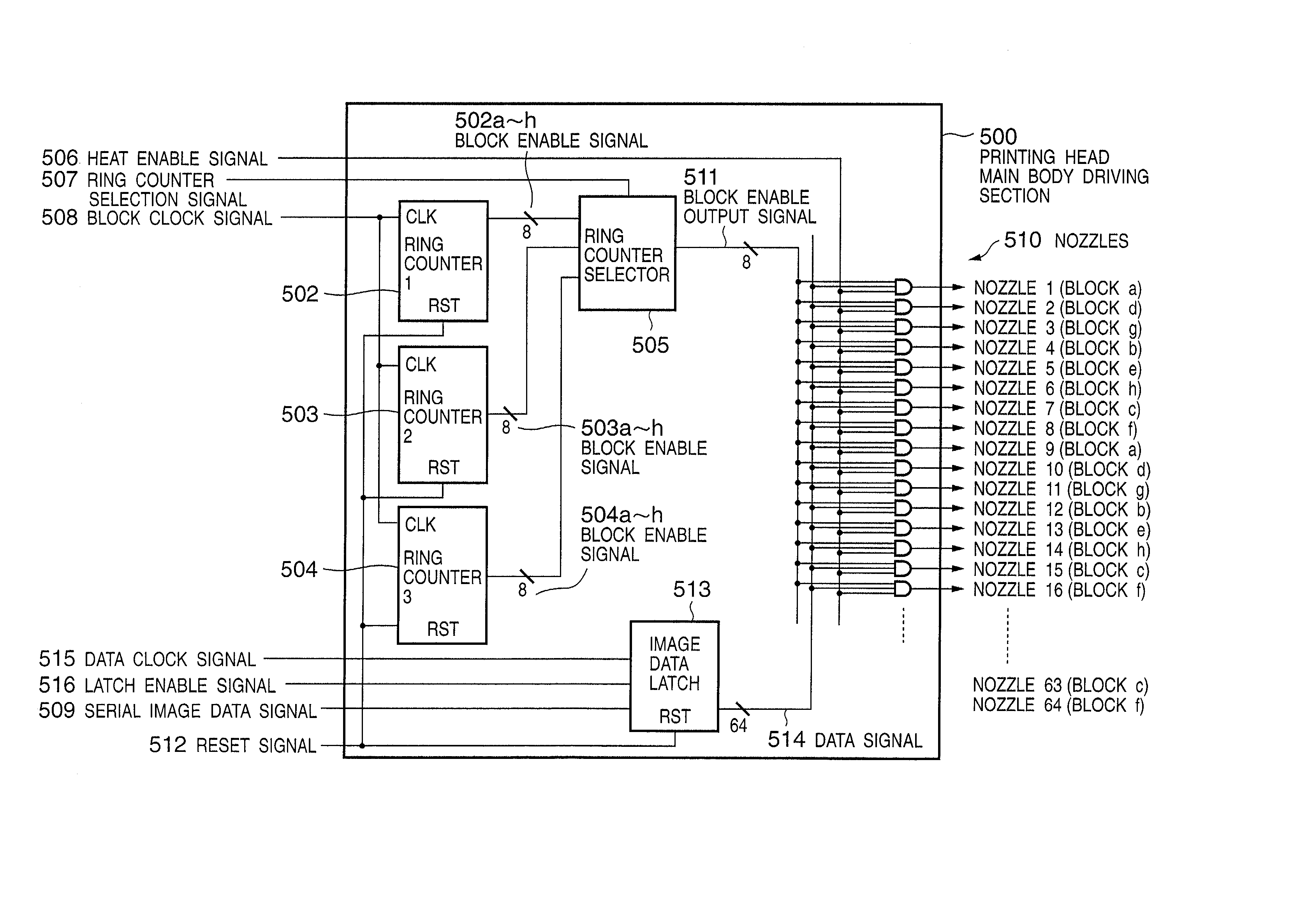
[0358] The printing head of the 13th embodiment changes the driving period of a specific nozzle at an arbitrary timing to minimize the influence of vibrations on the printing image quality without giving any periodicity to ink vibrations.

Problems solved by technology

This method is not suitable for an ink-jet printer which aims at low cost and small size.
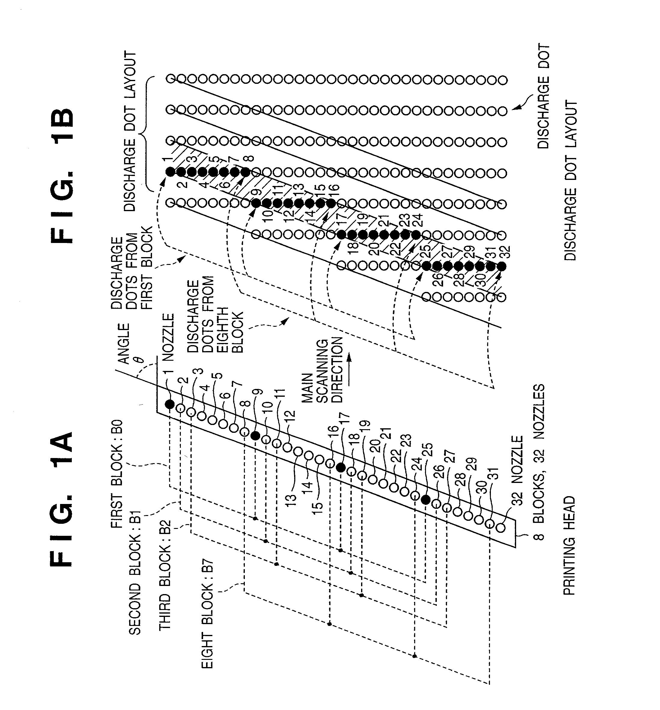
However, the following two problems arise when nozzles are grouped into several blocks, the nozzles are driven by the time division discharge method, and the number of nozzles (nozzle density) present in the printing head is increased to cope with the increase in speed.
First, the image quality is degraded by pressure interference (crosstalk) generated in ink discharge.
The printing head receives interference (crosstalk) owing to the pressure between nozzles that is generated in ink discharge.
The printing density changes every discharge nozzle in accordance with the nozzle driving order, resulting in low image quality.
In this way, ink discharge in the next period is influenced by the vibrations, decreasing the image quality of a printed image.
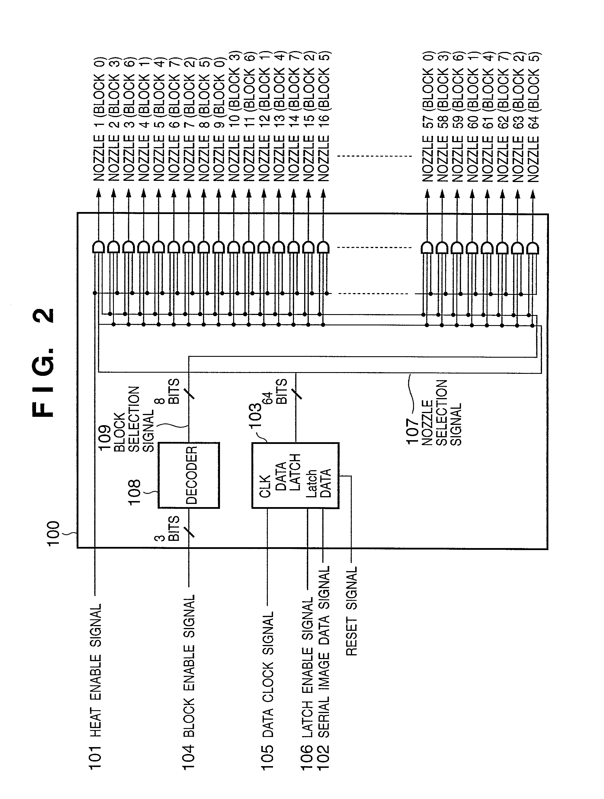
In the prior art, the nozzles of respective grouped blocks are driven in a fixed order, ink vibrations in the printing head may greatly vary periodically, and the influence of the vibrations becomes serious.
It is, therefore, difficult to achieve both prevention of degradation in image quality and high-speed printing.

Method used


Image

  • Printing head, image printing apparatus using the same, and control method therefor
  • Printing head, image printing apparatus using the same, and control method therefor
  • Printing head, image printing apparatus using the same, and control method therefor

Examples


example 2

[0366] [Example 2 of Driving Order Change Circuit]

[0367] FIG. 53 is a block diagram showing a driving order change circuit when the block driving order is changed using a barrel shifter capable of generating a predetermined driving order. FIG. 54 is a block diagram showing a circuit when block driving orders are stored in a memory in advance and sequentially read out to generate the block designation signal I_BE representing a changed driving order by a BE generation block.

[0368] When block driving orders are stored in the memory, as shown in FIG. 54, random driving orders are prepared as the driving orders. This can spread ink vibrations.

[0369] If the printing head 1310 is not assembled into the ink-jet printer main body, vibration avoidance information unique to a printing head is given to the printing head 1310, and the printing head can be controlled with high precision by using this information. For example, a printing head is tested in shipping, and block driving orders in FIG...


PUM


Abstract

This invention provides a printing head which can prevent an increase in the number of block enable signal lines, and can prevent changes in printing ink density caused by interference due to the relative pressures of nozzles generated in ink discharge, and an image printing apparatus using the printing head. For this purpose, an increase in the number of input signal lines along with an increase in the number of blocks is prevented using a block clock signal or the like instead of a block enable signal as an input signal to the printing head. Three ring counters generate signals having different nozzle driving orders. These signals are selectively used by a ring counter selection signal. Ink is not always discharged from the nozzles in the same output order. This can prevent changes in ink density caused by pressure interference.

Description

[0001] The present invention relates to a printing head, image printing apparatus using the same, and control method therefor and, more particularly, to an ink-jet printing head.[0002] An example of information output apparatuses for a word processor, personal computer, facsimile apparatus, and the like is a printer for printing information such as desired characters or images on a sheet-like printing medium such as a paper sheet or film.[0003] The printing method of the printer includes various known methods such as a thermal method and ink-jet method. In particular, the ink-jet method of discharging ink to print information has recently received a great deal of attention because of non-contact printing on a printing medium such as a paper sheet, and easy color printing.[0004] The ink-jet arrangement comprises a printing head for discharging ink in accordance with desired print information. The printing head prints information while reciprocating in a direction perpendicular to the...

Claims


Application Information

Patent Timeline
IPC IPC(8): B41J2/05
CPCB41J2/04521B41J2/04525B41J2/0458B41J2/04543B41J2/04573B41J2/04541
Inventor NAKAJIMA, YOSHINORIMORIYAMA, JIROMURATA, TAKAYUKIHIRAYAMA, NOBUYUKI
Owner CANON KK
Learn More