Prosthetic foot having curved ankle section

a foot and ankle technology, applied in the field of foot prostheses, can solve the problems of significant deficiencies in devices, long, heavy weight of prosthesis components, etc., and achieve the effect of natural stride and resilience of gai

Inactive Publication Date: 2003-07-31
PHILLIPS VAN L
View PDF2 Cites 28 Cited by
  • Summary
  • Abstract
  • Description
  • Claims
  • Application Information

AI Technical Summary

Problems solved by technology

However, each of the prior art devices has significant deficiencies; specifically, the component parts of the prosthesis, as in Lange, are too heavy and too rigid or, as in Poggi, are too massive and monolithic to respond properly to the nuances of stress-response gradients characteristic of the human foot.
Consequently, the wearer of the foot may engage in a wide variety of activities which were precluded in the past because of the structural limitations and corresponding performances of prior art prostheses.

Method used


Image

  • Prosthetic foot having curved ankle section
  • Prosthetic foot having curved ankle section
  • Prosthetic foot having curved ankle section

Examples


Embodiment Construction

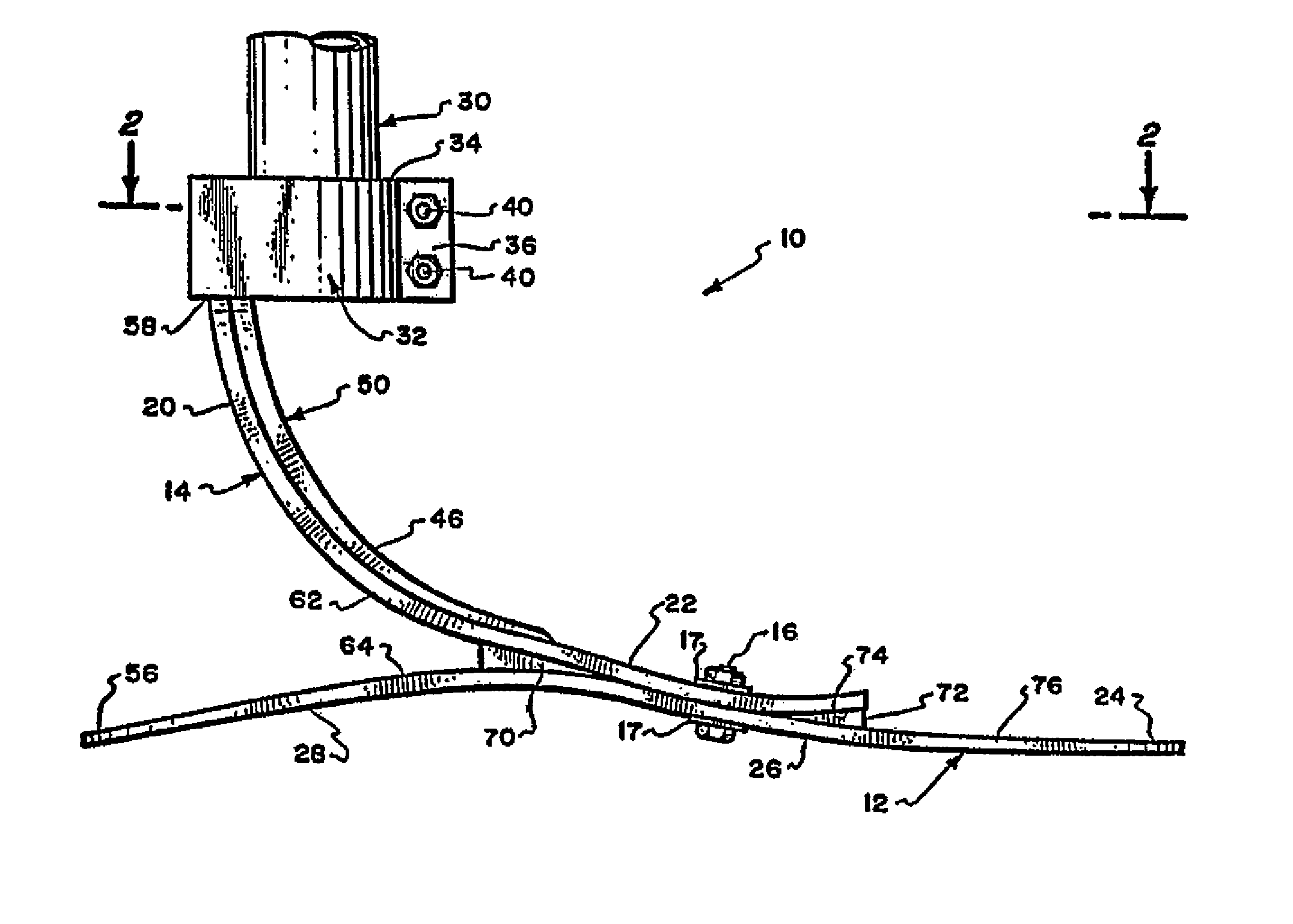
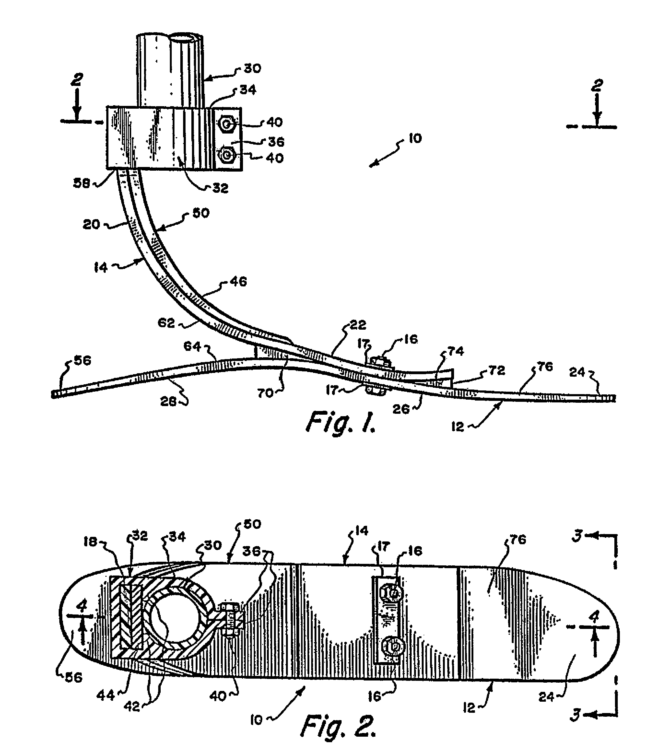
[0030] Referring to the drawings, and particularly to FIGS. 1 and 2 thereof, I show a foot prosthesis 10 constructed in accordance with the teachings of the invention and including a foot portion 12 and an ankle portion 14 operatively and demountably connected to each other by bolt and nut combinations 16 associated with loadtransmitting metallic plates 17. If indicated, the foot and ankle portions can be permanently secured to each other, as by epoxy adhesive, an intermediate resilient member, or the like.

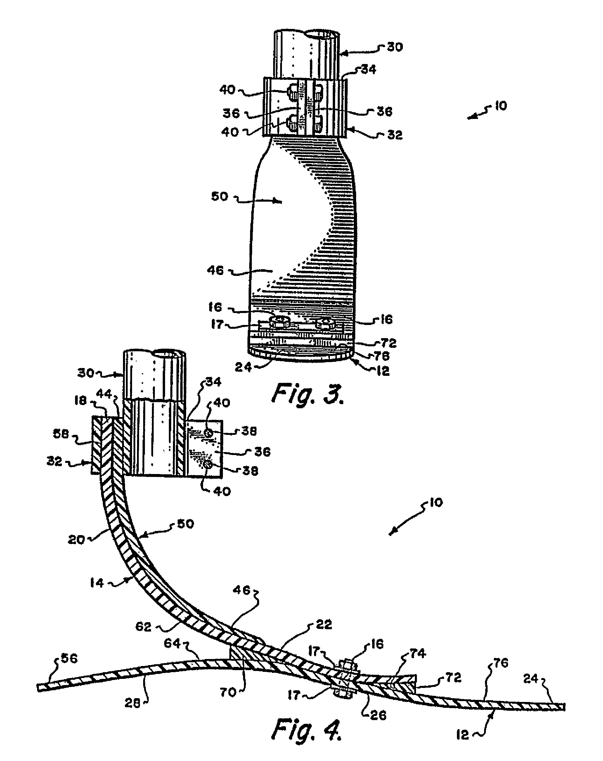
[0031] The ankle portion 14 of the prosthesis 10 includes a substantially rigid upper attachment section 18, FIG. 4, a curvilinear ankle section 20, and a lower attachment section 22. The sections 18, 20, and 22 of the ankle portion 14 are formed integrally with one another and simultaneously by a plurality of Juxtaposed, shaped laminae embedded in a hardened, flexible polymer.

[0032] The attachment section 18 has a rearward surface 58, as shown in FIG. 4, and a forward surface sub...


PUM


Abstract

Abstract of Disclosure A prosthetic foot characterized by a foot portion and an ankle portion. The foot portion and ankle portion may be fabricated from polymer impregnated and encapsulated laminates, including such laminates as carbon fibers and / or fiberglass or synthetic fibers such as Kevlar. The ankle portion may include an upper end positioned near or below about the location of a natural human ankle joint, a lower end, and an elongated intermediate section at least a portion of which curves downward and forward between the upper end and the lower end. The foot portion may be curved and have a heel section, an arch section and a toe section. The foot portion may be connected to a lower attachment section of the ankle portion, with at least the heel section of the foot portion extending rearwardly from the lower attachment section and below the upper end of the ankle portion.

Description

Related Applications[0001] This application is a continuation of U.S. Application Serial No. 08 / 991,082, filed December 16, 1997, now U.S. Patent No. 6,527,811, which is a continuation of U.S. Application Serial No. 08 / 727,772, filed October 8, 1996, now U.S. Patent No. 5,976,191, which is a continuation of U.S. Application Serial No. 08 / 532,530, filed September 22, 1995, now U.S. Patent No. 5,593,457, which is a continuation of U.S. Application Serial No. 08 / 270,231, filed July 1, 1994, now U.S. Patent No. 5,486,209, which is a continuation of U.S. Application Serial No. 07 / 977,654, filed November 17, 1992, now abandoned, which is a continuation of U.S. Application Serial No. 07 / 337,374, filed April 13, 1989, now U.S. Patent No. 5,181, 932.Background of Invention[0002] This invention relates to foot prostheses in general, and specifically to a prosthetic foot characterized by a unitary foot and heel construction, and / or an auxiliary ankle construction which permits the flexibility ...

Claims


Application Information

Patent Timeline
Patent Type & Authority Applications(United States)
IPC IPC(8): A61F2/00A61F2/50A61F2/60A61F2/66
CPCA61F2/601A61F2220/0083A61F2002/30433A61F2002/30464A61F2002/30467A61F2002/30469A61F2002/5007A61F2002/503A61F2002/5055A61F2002/5075A61F2002/607A61F2002/6657A61F2002/6671A61F2220/0041A61F2220/0075A61F2/66A61F2002/30462
Inventor PHILLIPS , VAN L.
Owner PHILLIPS VAN L
Why Eureka
Try Eureka